
Here is the completed deck assembly. The hatch openings have been cut out, mast hole cut out, a square piece of 3mm ABS plastic (the size of a postage stamp) has been glued to the underside and then a hole drilled and a metal tube inserted for the crewman's "rack". As per the plans the tube extends 40mm above the deck; and lastly the triangular foam block has been glued beneath. I used 5-minute epoxy for the ABS joints. [Pat Clear comments: "I would only recommend solvent type ABS cement."]

The rudder is made up of a number or ABS plastic pieces. You must shape the round piece and the triangular arm yourself. You also need to shape the leading and trailing edges of the rudder, sort of like an airplane wing.
|  |
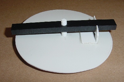
The round hatch must be cut from the same piece of ABS plastic used for both hatches. A hole is drilled in the middle and a small piece of angled plastic cut to act as a stop to prevent the crossbar rotating. (The plans don't show this well.) A large nylon screw and bevelled washer top it off. Later, the black foam gasket sheet will be attached and trimmed.
I painted the hull and deck separately before gluing them together. After the rudder and keel are painted and dry, they can be glued in place. By this time you'll want a boat stand. I made mine like a typical folding sailboat stand, but the plans include a template for a small non-folding stand.

Pardon the cluttered workbench! Notice the wires hanging down from the hull. All the servos and winches are trial-fitted before the hull and deck are assembled. They'll have to be installed before you can finish installing the rudder.