Return to introduction
ANNALS
of the
DUDLEY OBSERVATORY
Vol. I.
ALBANY
WEED, PARSONS AND COMPANY, PRINTERS.
1866.
116
The Swedish Tabulating Machine of G. & E. SCHEUTZ.
It is a well known fact that Mr. CHARLES E. BABBAGE was
the first to attempt the construction of a Difference Engine;
but owing to some misunderstanding between the inventor
and the English government, under whose patronage the
work was carried out, it was never completed.
In the Edinburgh Review for July, 1834, Dr. LARDNER
gave an account of Mr. BABBAGE'S machine, which, coming
under the eye of Mr. GEORGE SCHEUTZ, an eminent printer
at Stockholm, he conceived the idea of building one which
should do the work contemplated by Mr. BABBAGE, but on a
totally different plan, as regards the details of the mechanism.
After proving the practicability of his ideas in the
construction of some models, it was allowed to rest for a year or two.
In 1837, EDWARD, the son, took up the plan, and in
conjunction with his father completed a machine of small compass in
1840. This was exhibited before the Swedish Academy of
Sciences in 1843. On the certificate of that body, orders to
manufacture machines were solicited in different countries,
but without success. After numerous failures to secure
assistance from the Swedish government, for the purpose of
constructing a large and complete machine, finally in 1851, the
Diet with difficulty consented to advance 5,000 rix-dollars,
(about $1,500), on condition that the machine should be
completed within a year, and that the inventors should give a
guarantee to return that sum to the State if it did not prove
successful.
Having already expended all their means in the
construction of models and tools, they were unable to give the
necessary guarantee, and the invention would probably have been
abandoned, but for the noble liberality of fifteen members of
the Swedish Academy of Sciences, who became responsible
for the amount advanced.
117
The machine was completed in 1853, and performed its
work perfectly. In consideration of the successful issue of
the project, and the large sums that had been expended
by the inventors, the Diet granted a reward of 5,000 rix-dollars,
thus making the total grant 10,000 rix-dollars.
The machine was taken to England and exhibited before
the Royal Society of London, and also placed in the great
Paris Exposition, where the Gold Medal was unanimously
awarded to the inventors.
It was purchased for the Dudley Observatory in 1856, at
an expense of $5,000.
This machine was the only one built until 1863, when a
duplicate was made for the Registrar General's Office,
London, England.
This machine possesses a twofold power, with the mechanism
appropriate for each; not necessarily connected, though
simultaneous and automatic in its entire action. These functions
are, first, the production of certain numerical results; second,
the conversion of those results into a permanent legible record.
The theory of the machine is based on the mathematical
truth, that in any series of numbers, the nth order of
differences may be regarded as equal to zero, where n may be any
number whatever. To produce such a series by mechanical
means, the only condition necessary is that there be as many
variable wheels indicating the numbers as we have
differences. If n was a very large number, the mechanism would
become cumbersome and unwieldly. It is found in practice
that for the great majority of useful computations, four orders
of differences are sufficient.
This machine is constructed for four orders, and will
consequently compute any series, in which the fourth (or any
inferior) order of differences are equal.
118
This will be more easily understood by a simple illustration.
Suppose it is desired to tabulate the series of square
numbers beginning with unity. Let us first see how these
numbers can be produced by means of successive differences.
We arrange them for convenience in the following table:
| Number. | Square. | 1st diff. | 2d diff. | 3d diff. |
|---|
| 1 | 1 |
| | 3 |
| 2 | 4 | | 2 |
| | 5 | | 0 |
| 3 | 9 | | 2 |
| | 7 |
| 4 | 16 |
Having given the number (1) square of 1, and the first
difference 3 = (22 - 12) and the second diff.
2 = (32 - 22) -
(22 - 12), the squares of all successive numbers may be found
by continued additions.
The difference between (22 - 12) = 3 is the first diff.; the
second diff. (2) is constant. Then,
(3)2 = 9 = (2)2 + 1st diff.(3) + 2d diff.(2),
or 9 = 4 + (3+2),
or 9 = 4 + 5, (5) being the second number in column of
first differences.
And the same process may be repeated to any extent.
What now is required in a machine, is, first to be able to
produce the first order of differences, having given the first
difference 3, and the second difference (2) constant.
Suppose we have a wheel, on the circumference of which
is inscribed at equal distances apart, the numbers, 0, 1, 2, 3,
4, 5, 6, 7, 8 , 9. If this wheel should be set so that the figure
3 should coincide with a fixed mark, and by means of
simple mechanism, it should be made to advance two
119
divisions at every motion of a lever, we should successively cause
the numbers 3, 5, 7, 9, to coincide with the mark; and if
when the wheel has made a complete revolution, it should
cause another wheel placed by its side to advance one
division, the process may be continued so as to form the series of
first differences, in which every successive number would be
greater by 2 than the number preceding.
This principle of successive additions is exemplified in an
ordinary clock; for at every oscillation of the pendulum the
second-hand advances one division, and after this has made a
complete revolution, the minute-hand has also advanced one
division. By a slight change in the escapement wheel, the
second wheel could be made to advance 2, 3, or 4 divisions at
every oscillation. Hence it will be readily understood how,
by simple machinery, any constant quantity may be added.
Now suppose we have three wheels, placed one above the
other on a vertical (shaft) axis, on each of which is inscribed
zero and the nine digits, corresponding with a like number of
divisions on their surfaces. If the number 1 on the upper
wheel, 3 on the second wheel, and 2 on the third wheel, be
brought opposite a fixed or zero point; and the nature of
these wheels be such, that when set in motion by a lever from
right to left, the second wheel adds its number to the upper
wheel, and by a motion of the lever from left to right, the
third wheel adds its number to the second (being in this case
constant and always equal to 2); from this arrangement, we
will be able to compute a table of square numbers.
We begin by moving the lever from right to left; when 3
(the number on the second wheel) will be added to 1 (the
number on the upper wheel), making 4 the square of 2. On
moving the lever back, 2 on the third wheel is added to 3
on the second wheel, making 5. Moving our lever back
again from right to left, 5 is added to 4 on the upper wheel,
120
making 9, the square of 3. Repeating the process, we next
get 7 on the second wheel; which added to 9 on the upper
makes 16, the square of 4.
It is evident from the above statement that the series of
squares is developed by a process of addition, in which the
constant significant difference, increased by each preceding
first difference, generates the order of first differences; and
with the sum of the preceding first difference and square,
produces the series of squares. This principle is true for any
series, whatever number n may be.
It will now be readily understood, should we have a series
of wheels, ranged under each other, the nature of which
should be such that the series below should add its number
to the one above, we could produce any series of numbers in
which the fourth order of differences should be equal.
Plate IV is a perspective view of the machine drawn on a
scale of 1/9 the full size.
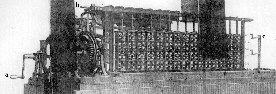
The successive orders of differences are represented by Δ0,
Δ1, Δ2, Δ3 and Δ4.
There are 15 vertical steel axles, each
passing through five hollow rings of metal, on which are
engraved 0 and the nine digits.
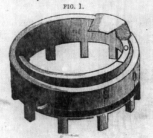
There is a groove cut around the circumference of each
ring, by which it is supported on a small brass shelf; being
121
free to turn about its center horizontally in either direction.
A perspective view of one of these rings is shown in fig. 1.
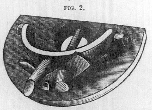
To each of the vertical axles is attached four brass shelves,
fig. 2 supporting small steel levers mounted on pivots. These
levers occupy a position directly underneath the rings (fig. 1) ;
their office being to add to the ring above the number
coinciding with the fixed mark engraved on the ring below.
When the machine is put in operation by means of
crank a, the lever b is moved out horizontally from right to
left, causing every one of the vertical axles to revolve from
right to left, thereby adding all the numbers on the row
marked Δ3 to those on Δ2, and all those on Δ1 to Δ0. By
continuing to turn the crank a, the lever b is moved back
again from left to right, this time adding the number on Δ4
to Δ3, and those on Δ2 to Δ1. This process is continued
long as the machine is kept in motion.
If we call the first axle to the right units, then the next
one will represent tens, and the next hundreds, etc. The
numbers on any row of differences is, therefore, read from
left to right, as in ordinary writing.
When all the rings are set at zero, by making that division
coincide with a fixed mark in front, no change will take place
in their position when the machine is put in operation.
The process of carrying for 10 will best be understood by
an example. Suppose all the rings in the first row Δ0 be set
122
at zero, except the last one on the right hand, which we place
at 5. Let all the rings on the second row Δ1 be set at 9. If
these numbers were written down they would stand thus:
000 000 000 000 005 = Δ0
999 999 999 999 999 = Δ1
Now when the lever b is moved from right to left, every
number in Δ1 will be added to Δ0, and the result will
stand thus:
999 999 999 999 994 = Δ0
It is readily perceived that the operation is not complete,
since we ought to have
Δ0 = 000 000 000 000 004
When the 9 is added to 5, making 14, the units ring, in
passing through zero, throws out a small lever (by means of
the projection between the numbers 7 and 8 shown in fig. 1).
As the motion of the machine is continued, the post c
carrying a lever arm passes in front of the rings, and by means of
the lever thrown out advances the second ring a unit, making
it zero, it in turn throws out the next lever to the left, when
the same process is repeated, and in this example all the rings
on the upper row, except the 1st, is left at zero.
In case any difference is negative, we get the same result
by adding the complement, or difference between the number
and 10. Suppose we wish to subtract 2 from 3, our result
would be 1. If we take the complement of 2 = 8, and add
it to 3, we get (10 + 1), or the same result on the first wheel
as before. If we wish to subtract
000 000 000 142 346
we must set on the machine the complement of this number
999 999 999 857 654
adding this complement is the same as subtracting the number
itself.
By changing all the rings in the 3d and 5th vertical
on the left, the computation can be made by the sexagesimal
123
system, that is, the results will at once be converted into
degrees, minutes and seconds.
Before starting the machine for any computation, it is
necessary to set the proper wheels, after which it needs no further
attention; for so long as the last order of differences is
constant, it will continue to produce the required numbers.
Thus for producing a table of squares, it is only necessary to
give the machine three numbers, 1, 3 and 2; and from these
data we can compute the squares of all numbers up to 30
millions. In the same manner, by giving the machine the
numbers 1, 7, 6, 6, we can produce a table of cubes, the limit
being 15 figures. The same principles apply in the
computation of logarithms, or any series of numbers whatever.
124
During the process of making the computation, the
machine also prints the result, together with the proper
argument, to 8 places of figures.
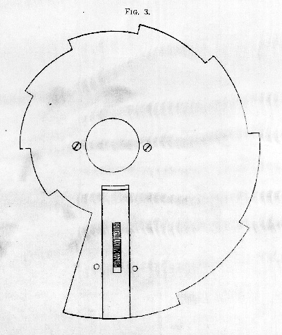
A portion of the mechanism for printing, is shown at the
left end of plate IV. The numbers on the upper row of
rings are transferred to the printing part, by means of "the
snail" attached to and revolving with the upper rings. This
contrivance shown in fig. 3, has long been used in the striking
part of the common eight-day clock.
The results may be stereotyped on strips of lead, or printed
on ordinary paper or card-board. By changing the position
of the carrying post on one of the rings, we at once obtain the
nearest whole number, no platter how many decimal places
are used in the computation. At the average rate of working
120 complete results are calculated and printed in one hour.
In order to compute any series of numbers, it is necessary
to determine the orders of differences belonging to that series,
which must be set on the proper rings.
The general formula is:
n = the number of the term.
a = the first term.
Δ1, Δ2, Δ3, etc. = the orders of differences.
Then we have the following form of equations:
(n = 1) = a.
(n = 11) = a + 10Δ1 + 45Δ2 + 120Δ3 + 210Δ4 + etc.
(n = 21) = a + 20Δ1 + 190Δ2 + 1140Δ3 + 4845Δ4 + etc.
(n = 31) = a + 30Δ1 + 435Δ2 + 4060Δ3 + 27405Δ4 + etc.
(n = 41) = a + 40Δ1 + 780Δ2 + 9880Δ3 + 91390Δ4 + etc.
125
For facilitating the computation, the binomial co-efficients
together with their logarithms, belonging to each order of
differences, are tabulated up to 80 terms. The solution of the
equations may also be abbreviated, by choosing such terms,
that the co-efficients in each equation will be multiples of 10,
100, 1000, etc.
If it is desired to set on the machine all the orders at the
same time, it is necessary to make a further reduction of
the quantities found from the equations. We prefer, however,
to set them consecutively, after the computation has begun.
It is found, from our own work as well as that previously
done with the machine, that it is occasionally liable to an
accidental error, from the failure of one or more rings to
perform its office. These errors are purely mechanical, and
are not to be confounded with the principles on which the
machine is constructed.
One of the first requisites is to hold the ring, on which
numbers are engraved, so that there shall be no side play,
and yet allow it to move with the necessary freedom. The
second is, to be able to destroy the momentum of the ring,
as soon as the motive force ceases to act. The latter condition
has been obtained by putting a "brake" piece on each
ring, consisting of a small piece of leather or rubber pressed
against its circumference, by means of a spring. The liability
of accidental error would be greatly lessened by connecting
ratchet wheels with each ring, so that it could only move
one direction. This would enable us to put more weight on
the adding levers, without any danger of disturbing the
position of the ring, when the motion of the shaft is reversed.
A little attention to a few of these points would secure an
almost perfect machine.
For bringing the type in line, previous to making the
impression, we have employed a brass roller in place of the
126
steel wedge. This roller is pressed between the type by two
rubber wheels, and is found to work admirably. The type
are always straightened, no matter what their position may
be, and without any possibility of injury to any part of the
mechanism.
Our past experience has led us to believe that such a
machine would be greatly enhanced in value, by the
addition of one or two more orders of differences; since in that
case, a much longer series of numbers could be computed
from one set of constants.
It would be an easy matter to apply motive power to the
machine, so that when once set, it shall be a complete
automaton, making its computations without the assistance of
any person. As soon as one set of constants are exhausted,
the machine will stop, and will also be made to give notice
of the fact by ringing a bell; upon which, a new set of
constants may be introduced, and the computations continued.