Back to Main Page
Plywood Cuts
- 60" x 20" x 1/2" Baltic Birch 9-ply birch plywood
(this is 1/3 of a 5' x 5' sheet, cut in direction of surface grain)
- Cut in strips (with surface grain) as shown:
15: 1" wide strips
1: 2" wide strip
- Round long edges of all strips
(using 1/4" round router bit)
- From the 1" strips cut:
A: 18 strips 24" long (from 9 of the 60" strips)
B: 12 strips 25" long (from 6 of the 60" strips)
- From the 9 remaining 12" long strips cut:
C: 4 pieces 7" long plus
D: 4 pieces 4½" long (each C+D from 1 strip)
E: 3 pieces 7¾" long (see 4th E piece below)
F: 4 pieces 5" long (2 each from 2 strips)
- From remaining 10" strips cut:
E: 1 piece 7¾" long (completes E set above)
G: 4 pieces 9" long
- From the 2" strip cut
H: 2 pieces 11" long
I: 2 pieces 4" long
|  |
Aluminum Cuts
- 1" aluminum angle bar
- 1/8" thickness x 4': 4 pieces
- cut all 4 pieces in half
- 4 of the 2' pieces are for side splash rails
- cut remaining 4 pieces to 10" + 5" + 2" + 2" (brace parts)
- cut two 1-3/4" pieces from scrap (for gunwales)
- 1/16" thickness x 4': 1 piece
- cut 2 20" pieces (for end splash rails)
- cut 4 2" pieces (for center braces and splash rail hinges)
- 2" wide x 1/8" thickness aluminum strip: 1 piece
- cut 2 each 9" + 5-1/2" + 4" + 1" + 1" + 1/2" + 1/2",
(brace parts, hinges, hooks)
- cut both 4" pieces in half lengthwise (brace parts)
See detail drawings below for additional finishing (cuts, rounding and drilling).
Wood Parts Finishing
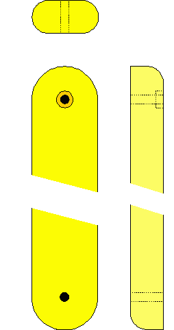
- All drilled holes are 3/16" diameter to accept 10-32 machine screws.
- Wood parts: (see plywood cuts for cutting from stock).
- All wood parts are 1/2" baltic birch plywood.
- Nearly all are 1" wide strips.
- Long edges of strips are 1/4" rounded (as shown at top right).
- Ends of stringer strips (the long ones) have holes drilled 1/2"
from ends. All the but two of the A's and all the B's
are 1/2" rounded on both ends as shown at right. The two remaining A's are
rounded at one end only (the other end attaches to the gunwale).
Depending on where they are used in the frame, some holes are countersunk
for the head of a flathead screw or drilled out 1/8" deep to receive a 10-32 nut.
I use a 3/8" wood hole drill bit and
sink it through about three plies. This is deep enough that all the
screw treads will engage, but not quite flush with the surface. The
hole will be a little tight, so I tap the nut in with a hammer or press
it in with vise-grips.
Hole locations:
Stringers:
- A: All 24" pieces have two holes, 1/2" from ends (23" center-to-center).
- B: All 25" pieces have two holes, 1/2" from ends (24" center-to-center).
End braces:
- D: The 4½" long pieces have two holes, 1/2" from ends (3½" center-to-center).
- E: The 7¾" long pieces have three holes, 1/2" from ends and at 3½" from hole toward middle of brace (to match spacing of D holes).
Mid braces:
- F: The 5" long pieces have two holes, 1/2" from ends (4" center-to-center).
- G: The 9" long pieces have three holes, 1/2" from ends (8" center-to-center) and centered between them at 4" (to match spacing of F holes).
- C: The 7" long pieces have three holes, 1/2" from end toward middle of brace, 4" from that (to match spacing of G holes) and 1-1/2" from that. (the outer end of this piece will be trimmed at an angle).
Parts Finishing (Gunwale)
All drilled holes are 1/8" diameter to accept 1/8" pop rivets unless otherwise indicated.
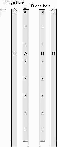 Gunwale rail parts: 1/8" thick 1" x 1" angle bar. Four two foot long
pieces are finished on the ends and drilled as shown at right (two
A and two B).
Rivet holes are spaced 3" apart; pop rivets are used to attach heavy duty snaps (male
halves).
Snaps alternate between outside (under the angle) and inside (on the face), with 4
snaps on the outside of each rail and 3 on the inside.
Hinge and brace holes are 3/16" diameter, 1/2" from end and edge.
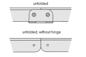
Hinge assembly details:
- 2" x 1" flat piece with holes 1" apart:

- 1-3/4;" angle piece with holes 1" apart, finished as shown:

Assembled hinge, in folded and un-folded views:
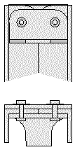
 Gunwale end parts: 1/16" thick 1" x 1" angle bar:
Two 20" pieces are finished as shown at right, with snaps riveted to the pieces, 4
under the angle, two on top, and two on the inside (to mate with the mid brace). Two
straps, not shown, are fastened to the rail with the middle side rivets. They wrap
around the mid brace and snap to the top snaps, to secure the rail to the brace.
Other hooks and catches (from 1/8" flat stock):
Hooks: two 1" x 1½" pieces finished as shown; to join end of top mid
stringer to top of mid brace.

Catches: four 2" x ½" pieces finished as shown; to join horizontal
center brace to vertical center brace.

Parts Finishing (angle braces)
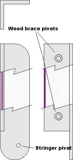 The brace parts fashioned from angle stock will consume the remaining 1/8" 1" x 1"
stock. All these angle bar brace pieces must have a 1" notch cut in the lower end with
one hole 1/2" from lower end of long side (for stringer pivot). Note that
these holes must be offset 1/2" from inside of angle bar to allow folding
(3/8" from outer edge).
Holes for the wood brace pivots are centered at 1/2" from both
edges of outer face, spaced as indicated.
NOTE: All braces are mirrored. In the end you will have two 5" long left-hand
braces, two 5" long right-hand braces, etc.
- AA: Four 5" long pieces (for end braces), 2 holes 1/2"
from each end of 4" side (3" on centers).
- BB: Four 10" long pieces (for mid braces), 2 holes 1/2" from each end of
9" side (8" on centers) and 3rd hole at 5" from lower hole.
- CC: Eight 2" long pieces (for all braces), 1 hole centered in the 1" side.
Rounding:
All the angle brace pieces need to be rounded at the bottom where they will
press against the skin. Other corners can be rounded just to knock off the
sharp corners. Same with the edges.
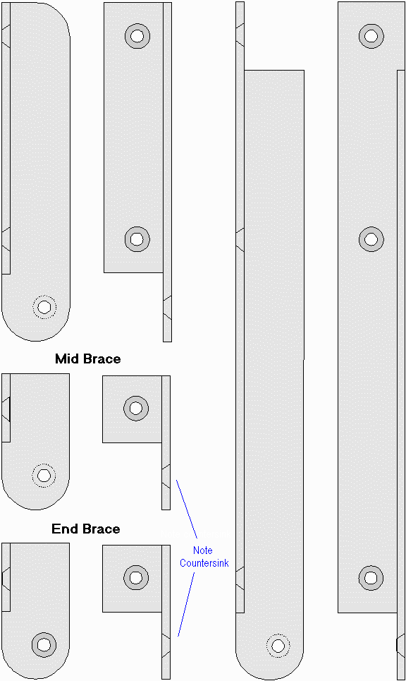
Countersinking:
All the holes on the short sides where the angle braces attach to the wooden
brace parts are countersunk on the inside of the angle for the head of a
flathead #10-32 screw.
The holes on the bottom end of the long sides where the braces attach to the
stringers are countersunk on the outside of the angle, except for the 2" pieces
for the end braces, which get countersunk on the inside.
The full-scale drawings on the next page show these countersinks.
Notching:
There is a 1" notch in the upper end of the 10" pieces that wasn't mentioned in
the previous paragraphs. This is to allow for the gunwale end assembly.
Here are full-size drawings of one half the brace parts. The other half of the
parts are mirror images.
Parts Finishing (flat bar braces)
METAL PARTS (see aluminum cuts for cutting
Brace parts: 1/8" thick 2" flat bar:
- DD: The 5½" pieces (for end braces), 2 holes 1/2" from bottom end
and 1" apart, 2 holes 3" above them (to match spacing on part A). The
top corners of this piece are notched to leave a 1" high by 1/2" wide
projection in the middle.
- EE: The 9" pieces (for mid braces), 2 holes 1/2" from bottom end and
1" apart, 2 holes 1/2" from top end and 1" apart. The top end of this
piece is notched in the middle, 1/8" wide by 1-1/2" deep (to accept the
hook on the end of the top middle stringer).
- FF: The two 4" pieces are cut in half lengthwise to make four 1"
wide pieces 4" long. Each of these has two holes, 1/2" from each
end (3" on center, to match upper hole spacing on part B).
Stringer Assembly
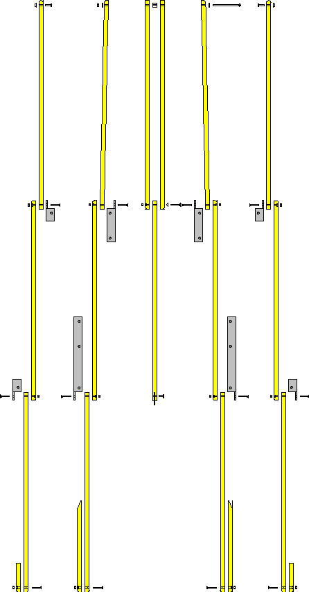 Drawing shows half of frame in exploded view.
Note that some end edges are rounded and some are not. (Ends of stringers that are
sandwiched between another stringer and a brace piece have edges left flat; outside
edges are rounded.)
This drawing also shows which side of angle brace parts are countersunk for the
flathead machine screws, and which stringer holes are countersunk for screws or
nuts.
The top center stringer is slotted for the hook that engages the middle brace. The
hook is held in place with a 1/2" pop rivet.
Pop rivets are also used to hold snap halves to the end side stringers.
The 3" roundhead screw in the end is not countersunk; it holds the rubber ends of the
side stringer strap.


 Gunwale rail parts: 1/8" thick 1" x 1" angle bar. Four two foot long
pieces are finished on the ends and drilled as shown at right (two
A and two B).
Rivet holes are spaced 3" apart; pop rivets are used to attach heavy duty snaps (male
halves).
Snaps alternate between outside (under the angle) and inside (on the face), with 4
snaps on the outside of each rail and 3 on the inside.
Hinge and brace holes are 3/16" diameter, 1/2" from end and edge.


 Gunwale end parts: 1/16" thick 1" x 1" angle bar:


 The brace parts fashioned from angle stock will consume the remaining 1/8" 1" x 1"
stock. All these angle bar brace pieces must have a 1" notch cut in the lower end with
one hole 1/2" from lower end of long side (for stringer pivot). Note that
these holes must be offset 1/2" from inside of angle bar to allow folding
(3/8" from outer edge).

 Drawing shows half of frame in exploded view.