PakYak PlansVersion 4.0


Click to visit other pages |
PakYak PlansVersion 4.0
Click to visit other pages |
 At left is a view of the center brace and gunwale parts just before assembly.
First the prongs on the side brace go through the holes in the gunwale brace (this is a frame assembly step).
Then the gunwale (which is attached to the skin) is slid into the bracket on the top of the gunwale brace. The gunwale is tipped slightly outward when inserted, then tipped up to vertical. When the gunwale is tipped up, holes in the inside of the gunwale engage protruding ends of the bracket rivets
Then the clip hanging from the gunwale is inserted under the ends of the side brace prongs. This secures both the gunwale and the side brace.
| The drawing at right here is a top view of the side brace, showing the prongs that go through the hole in the hole in the gunwale brace. The prongs are shown as one piece here, but may be split in the middle if needed to accomodate the clip. The prongs are held in place by pins inserted in holes drilled through them from the edges of the side brace. |

|
| This next drawing shows the gunwale and gunwale brace before assembly. The clip and strap are shown above the gunwale, but are normally left snapped to snap halves on top of the gunwale hinge. |
| The next drawing is a full scale drawing of the clip and the top end of the gunwale brace (side view). The clip is made from a 2" section of 1" x 1" x 1/16" angle bar, with one flange bent to fit around the gunwale. The angle of the bend and the cut on the gunwale brace is about 18°. (The cut is on a line from 3/8" on the top edge to 1 1/8" down the side.) |

|
The top drawing shows a side view of the gunwale end piece with the nylon straps that will secure it in place.
The middle drawing shows a top view of the end piece and the gunwale side rails ready to be put in place.
The side rails go in place first, with the small tabs hooking around the ends of the mid brace.
Then the end piece snaps in place, over the projecting part of the mid brace vertical angle bars. As shown in the lower drawing, the top tabs in the end piece go over the side rails, and the side tabs go outside the side rails, locking the side rails in place. Note that the end piece now holds the brace straight.
Finally the nylon straps wrap around and snap to the top of the end piece to secure it in place.
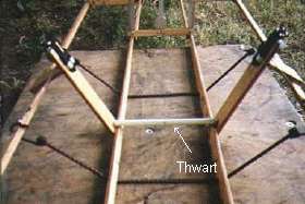
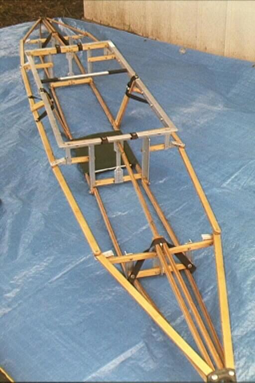
The lower thwart is a 10" long piece of 1/2" PVC tubing with a 10" length of wooden dowel pressed into it. Round-head screws are inserted into the ends so that they project about 3/8". 1/4" plastic collars on the screws make the lower thwart piece look about like this:
This loose piece is inserted into place after the rest of the assembly is done (can be inserted when on the water). Skin tension keeps it from coming out. In disassembly, it is removed after the side stringers are disengaged from the center brace. The side view of the center brace below shows the location of the 3/8" hole that the lower thwart end pin engages.
The lower thwart piece stores inside a paddle shaft, in one end of the upper thwart.
 (Top View) |
 |
This design feature keeps the side stringers from bowing inward. A thin metal cable is used in place of the nylon strap that is shown in the v4.0 drawings and photos. The cable is an improvement over the strap, as the cable does not stretch so the bracing is more firm.
In the photos below, the purplish/pink lines are the cable running from the bottom of the midbrace (from the bottom outside corners) up around the top of the endbrace (underneath the top stringers).
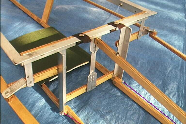 NOTE: the cable anchor points at the bottom of the Midbrace (Pan-head 10/32 bolt with washers to clamp the cable) |
 Cable runs up over the top of the Endbrace, under the top stringer, & back to help stop the back section from pivoting upward from the bottom of the Midbrace |
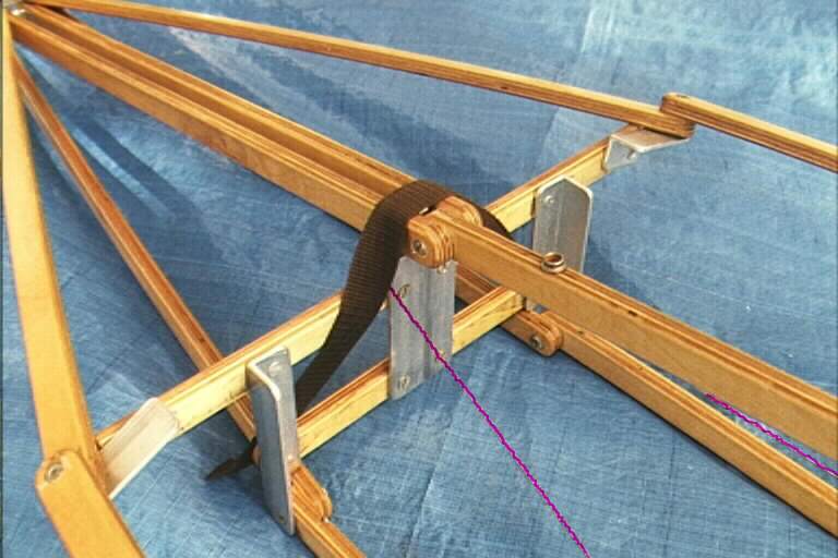 This cable minimizes the "broken-back whale" effect. Use something that doesn't stretch much, like polyester cord or steel cable. |
If you lift up the midbrace so the bottom is about the level of the top of the endbrace (prop it up on some books) then run the cord or cable around at that time and securely fasten it -- when you remove the books and set it back down it should tighten up and stop the endbrace from further upward movement. This may take a little adjustment to get just right, so if you are using steel cable I wouldn't clamp and cut off the far end just yet. Just pinch it between 2 washers with the panhead 10/32 bolt tightened down to hold it in place.
The results are striking, as Royal's second launch demonstrates.