PDF (15Mb)

U. S. NAVY
BUREAU OF AERONAUTICS
WASHINGTON, D. C.
U. S. NAVYFIVE FOOTTARGET KITE
Note:
SPECIAL DEVICES SECTION |
| Section 1. | General Description | 4 |
| Section 2. | Flying the Kite | 4 |
| Section 3. | Adjusting for Flight | 8 |
| Section 4. | Use as a Target | 9 |
| Section 5. | History and Adaptations | 12 |
| Section 6. | Specifications | 13 |
| Section 7. | How to Make the Kite | 14 |
| Section 8. | Reel and Flying Bar | 16 |
| Section 9. | Assembly | 17 |
| Section 10. | Substitutions | 18 |
| Section 11. | Unpacking and Packing | 19 |
| Section 12. | Repairs | 19 |
The U.S. Navy Target Kite, Mark I, functions as a maneuverable aerial target. It is a two-stick, diamond-shaped "Eddy" pattern kite of five-foot span and is usually flown at a range of 150-200 yards, Because of its unique control it can be maneuvered across the sky at a vertical angle of about 45 degrees and over a lateral course of about 90 degrees, although under the best operating conditions these angles increase. The available wind determines the extent of operation and control. In a 20 knot wind, the speed across the sky is about 40 m.p.h, The kite dives at about twice its lateral speed. Its extent of control is so complete that it can be looped or put through vertical and horizontal figure eights. Skillful manipulation by the kite operator can give a gunner a very thorough workout at a moving target in practicing lead and in manipulation of turrets. In a calm or light wind, the kite may be operated from an auto or a rail car. At sea it may be flown from the deck with the moving ship generating its own wind.
Operation is by means of two lines which extend up to the kite from the ends of a control bar about 4 feet long held horizontally by the operator. A reel may be combined with this bar. Near the kite the two lines connect to the ends of a horizontal bridle stick, from which control cords extend to a rudder at the foot of the kite. Yawing of the control bar by the operator swings the rudder by means of this linkage. When the rudder is kept in line with the vertical axis, the kite is inherently stable. It has no tail. A slight movement of the rudder causes the kite to veer across the sky; a full movement throws the kite into a loop; a full movement followed by a quick aligning of controls puts the kite into a dive from which it can be readily recovered by a quick rudder pull, after which the kite climbs back to its ceiling. Skill in operation is readily acquired and the operation can become a contest between the kite operator and the gunners.
Shooting down the kite is far more effective than puncturing a sail or sleeve. The most vulnerable point on the kite is cross axis of the two sticks, which corresponds to the pilot, gas tank and engine area of the airplane painted on the cover. A hit there brings the kite down like a dead duck. Hits along either stick often bring down the kite. A clipped control line usually puts it out of control. On the other hand, the kite provides an interesting display of marksmanship before a well-placed hit brings it down. One of the kites which was intentionally lowered to count hits, had 67 holes in the fabric and 7 more through the sticks but was still flying.
A downed kite can be put back into service in short order. A new stick is easily inserted, holes in the fabric patched, and severed lines knotted. Even if the kite is completely destroyed, the loss is small. Operating cost is a small percentage of that of an airplane-towed sleeve, moving target car, or target airplane.
An issue of 25 kites, 2 reels with lines, a kit of spares, and an instruction manual.The manual includes drawings and directions for making additional kites on the station.
THEORY
This form of kite is inherently stable. The win pressing the fabric each side of the mast forms the cover along that line into a vertical keel. The fin augments this keel surface and, being at the bottom, adds to the steadiness. The addition of the rudder provides a means of variable pressure against the air stream flowing along the keel and steers the kite. Proper manipulation of the rudder by pulling either of the two flying lines maneuver the kite. The rudder action is amplified by the pulling of the control lines on the spar connection, which inclines the kite surface toward the direction of pull so that it reacts like the sail of a boat. The recovery of the kite from each maneuver is facilitated by its stableness and its natural tendency to climb. With these features in mind, it becomes easier to study the kite's action, to control it in various aerobatics, and to determine the amount of pull on each line needed for each maneuver. Learn gradually. Feel out each action. Skill is easily acquired.
CONDITIONS
Choose a large open area for flights. The presence of hills, buildings, trees, and, other ground irregularities produces bumps and swirls in the air which influences
the kite's behavior. Wind should be strong and steady. A light wind makes the kite "lazy". Too strong a wind intensifies the control, requiring greater skill for recovering from acrobatics. It also exerts such pressure on the kite as to reduce its to arc laterally into the wind.
The better the flying conditions, the better the flights; however, because of this kite's unusual controllability, it can be opened even under adverse conditions.
THE TAKE-OFF
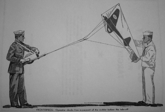
After adjusting the kite (see Section 3), hook the flying lines to the ends the bridle stick. If the reel is used, have an assistant carry the kite about a hundred feet leeward. If the flying bar with fixed lines is used instead of the reel, it will be necessary to carry the kite out to the full extent of the line on the bar. Having arrived at the take-off distance, the assistant should hold the kite inclined slightly forward while the operator yaws the flying bar back and forth and checks the free and full action of the rudder (see frontispiece). Make sure that the flying lines are even and clear. Now, holding the reel or flying bar level so that the rudder is neutral, call the assistant "Up." As he heaves the kite straight upward, lean back or take a few backward steps or a few turns in on the reel and the kite will rise.
If the flying bar is used, keep the rudder neutral while the kite climbs to its zenith. If the reel is used, hold the brake or handle while the kite gains altitude; then ease off on the brake and let the kite pull itself out to the range desired.
ATTITUDE OF KITE IN FLIGHT
Observe how the kite behaves. When first launched at a short range, it climbs high; but the weight of the full length of its line will pull it down somewhat so that its face is more squarely to the wind. In this attitude its control is more positive.
Although every effort is made to have the kites of standard construction and similar performance, some of them may have individual characteristics. Checking of the items for adjustment will minimize these variations. If, however, the kite should porpoise or luff vertically, an adjustment of the bridle is necessary. Bring the kite down and loosen the Lark's Head connection on the bridle stick; lengthen the upper end of the bridle line so that when the screw-eye E-1 is held at the side of the kite, it will be slightly below the spar. An adjustment of the bridle-point above the bridle point would be required if it flew too low, or had too wide an angle of attack. A high bridle adjustment is also advisable in a very strong wind, reduce the pressure on the face and to increase the soaring effect. Usually, however, bridling to the point even with the corner of the kite is the standard connection. After any alteration of the bridle line is made, it is necessary to adjust the control lines also.
CONTROL
Across the sky. With the kite flying steadily and exerting a firm pull on the lines, try some maneuvers. Yaw the flying bar slowly a few inches to left. The kite will lean in the corresponding direction and move across the sky to the left. Next, bring the bar back to neutral; the kite will come erect and move back to center. Now try a movement to the right and recover. Practice these while feeling out the response of the kite. As you learn the kite's ability and improve its control increase the extent and rapidity of your movements. If the kite leans to far and starts to lose altitude, give it reverse control quickly and it will recover. Continue to increase the lateral control until you can veer the kite back and forth over an arc of at least 45 degrees each side of center, but keep it from nosing down into a dive. The limit of lateral swing is reached when the kite lays way over into the wind, can go no further, and slowly begins to slide downward. Then slack off and let it come back to neutral.
LOOPS
When the sideways control has been mastered, try a loop. Let the kite climb to its Zenith; always have plenty of sky under the kite when looping, because conditions may cause it make a larger circle than anticipated. With the kite flying steadily at center, yaw the flying bar a full quick pull to the left; the kite will nose over leftward and circle down; keep the bar yawed and the kite will continue on around and up, but as it nears the top, bring the bar back to neutral. There is now a full twist in the line but this does not alter the method of control and but slightly affects the ease; in fact, the control remains about the same even with five or six twists in the line. Try a right loop next. As you loop it one way or the other, keep a mental count of the twists so the line can readily be unwound to neutral my means of reverse loops. After making a number of tight loops try circles of larger diameter in each direction. These require a smoother feel of control and a better estimate of distance. In light winds when the kite may seem a bit reluctant to nose over, rock it backward in the reverse direction from the loop you intend to make, then pull it over into the loop.
FIGURE-EIGHTS
This maneuver develops exactness of coordination and ability to recover the kite from various positions. In describing the kite's aerobatics, it is helpful to imagine a huge vertical clock face on the sky in the plane and area where the kite is flying, for a leftward figure-eight, the kite starts at "12 o'clock;" yaw the flying bar to the left as though to let the kite begin a loop but as it gets to "7 o'clock," give the bar reverse control and hold the kite in a right loop for a full circle; as it reaches the top of that loop, give an easy left, control and finish the right half of the top loop, neutralizing the controls as the kite reaches "1 o'Clock". It will be found that any reverse or recovery movement should be started just before the kite finishes the previous evolution; this makes the action smoother and avoids any loss of control. Practice both right and left figure-eights and both vertical and horizontal figure-eights until you are adept at reversing the controls.
DIVE BOMBING
The most spectacular maneuver by this kite is its vertical dive and recovery, imitating the descent of a dive bomber. To perform it have the kite at "12 o'clock" and yaw the flying bar as for a loop; but as the kite reaches "2 o'clock," quickly move the control to neutral and hold the kite inverted. It dives very fast, so you have but a few seconds before you must pull the controls for a recovery. Inasmuch as the controls are reversed and the speed makes them more sensitive, agility is required to hold the kite in a straight course. Before it gets too low, give the flying bar a firm yaw to recover; not too abruptly, because the kite is under a strain and should not be snapped out. You will observe that the opposite end of the flying bar must be pulled in order to recover from a right or left dive without twisting the line. However, when. the kite is rushing downward, in your first trials of this maneuver do not stop to debate which way to pull the bar; pull it either way or there will be a crash landing instead of a kite. Limit the first dives to long "S's" with plenty of sky underneath, Observe how the kite responds -- whether it recovers better to one side or the other, as it usually does; then try to see how small a curve you can bring it up in. These tests will show you how low, the kite can dive before you must recover. Meanwhile you will be learning how to make it dive straight instead of wavering.
Another type of dive is a long downward arc in which the kite dives toward some imaginary objective a hundred feet or so either side of the center.
HOVERING
In swinging the kite across the sky, you learned that it finally reached a location where the side pressure on the slanted kite which had sailed it over to it's extreme corner, was neutralized by the wind pressure coming toward the kite. At that extreme the kite wavered. It would try to get free and race back to center, or tended to nose into a dive, while you tried to force it over a few more degrees into the wind. In a somewhat similar balancing of forces, the kite can be made to hover at different heights or lateral angles by adroitly keeping it over on its beam sufficiently to prevent its regaining the proper rising attitude but not far enough over as to go into a dive. In regaining altitude after a hovering stand, it is important that you ease off the flying bar from the side at which you are holding the kite; otherwise, you would pull it over into an outside loop with probably insufficient altitude for a pull-out.
SLOW DESCENT
By laying the kite over on its beam a triffle further than is used when veering across the sky but not far enough to go into a dive, you can spill enough wind from the kite to reduce its lift, making it slide off sideways and downward rather slowly.
FORCED LANDING
Successfull performance of this maneuver without a crack-up calls for the best skill in this catalog of tricks. It comprises setting the kite down on the ground at its distance of flying line. The sequence starts with an arcing dive and merges into a hovering close to the earth. Here the wind is more bumpy than at higher levels and you must make recoveries quickly; you must anticipate how the kite is going to buck, and meet it with a reverse control, before the dip gets well started. In this manner bring the kite closer and closer to the earth and finally as it is about to touch, let out the reel, or run quickly forward or if using the flying bar, let go, so that the kite will fall back on the ground. This maneuver is peculiarly useful when, after "cease firing," you are lowerig the kite to count bullet holes.
COMBINED MANEUVERS
The order of the foregoing aerobatics is that of progressing ability, but they can be performed in any sequence when the kite operator and the gunners are. competing. It is probable that the operator will devise other stunts. The idea is to gain complete familiarity with the kite in order to make it an evasive and instructive target. As explained, individual kites have their unique characteristics so the kite operator will
do well to prepare himself by giving the kites he is to use a preliminary flight so that he is assured that all is in readiness and that no lack of preparation on his part will hold up the gunners.
Splendid practice for two kite operators is to have a kite fight. Two operators stand about a hundred feet apart and fly their kites at about the same length of line. As the two kites chase each other about the sky, it will call for every bit of skill each has acquired.
After, a crack up of the kite, it is easiest to lay the reel or flying bar where you are and go after the kite, disconnecting the two flying lines from the bridle stick. Bring in the wreck and reel in the line. If the kite comes down in rough or wooded land, it may be better to cut off the snaps so that as the line reels in there will be nothing to catch or snarl.
LANDING THE KITE
The forced landing method previously described may be used, particularly when some minor adjustment is to be made. Another way of landing the kite with the line out is to run it down. Have an assistant step in front of you and extend his arm up and over the two lines; then run forward toward the kite with the lines running under his armpits. As he approaches the kite, it will incline more steeply as it gets lower. When finally the runner is close to it, the kite will probably weave back and forth. It may be necessary to stop a moment and guide the lines to steady the kite. Then, when within about twenty feet of the ground, a swift run forward or an adroit handling of a slacked line will effect a safe landing. This method is necessary when a fixed length of line is used in connection with a plain flying bar without a reel. The same idea can be employed in a limited space by having one assistant wind the line an the bar while you walk as far as convenient toward the kite -- fifty feet or so at a time -- and then walking backwards toward your assistant to give him the slack. Repeat this process until the kite is brought in.
When a reel is used, wind in the kit until it is about fifty feet overhead. From there it can be force-landed, brought down to the hands of an assistant, or swooped down, letting out some line as it nears the earth so as to neutralize the wind pressure. Under steady wind conditions, the kite can be reeled right down into the operator's hands, or set down without damage a few feet away.
Before each flight, after each hard landing, and whenever a kite fails to perform correctly, check the following items: (1) The wing nuts tight. (2) Spar at right angles to mast. (3) Boltrope taut and tied. (4) Fabric of cover even each side and top and bottom, without looseness, unevenness or pockets. (5) Bowing line secure at ends, with the extent of bow in accord with prevailing wind; (distance between spar and bowing line usually about 8"; light winds about 3" but never more than 9" in heaviest winds.) (6) Pintle secure (7) Control lines adjusted; To do so lay the kite on the deck, face up, pull up on the bridle stick so as to tilt up the lower end, and place the toe of your foot on the upper point of the kite to hold it. This attitude facilitates aligning of the controls. (See Fig. 1). Hold the bridle stick so that both ends of the bridle are tight; note the passing of the control lines through the screw-eyes B-1 and be sure they are not kinked. Now tilt the bridle stick so as to pull the rudder in direct line= with the fin; then adjust the button-slides until the bridle stick is horizontal and parallel to the deck with the rudder neutral. Finally, slack off the button slides slightly so that there is less tension on the control lines than on the bridle, thus making the rudder operate more easily.
A very important item to maintain in adjustment is the length of the two flying lines. The manufacturer should deliver them the same length; but after being used, one may stretch somewhat. Uneven winding may alter the length. Knotting after breakage will reduce the length. When the flying bar is in use, it can be yawed a bit to compensate for small differences; but any large variation should be corrected by cutting of the extra length and re-tying at either end. When using the reel, one of the winding drums can be turned to compensate for inequalities, as described in Section 8.
ON THE FREE GUNNERY RANGE
WITH NATURAL WIND
The layout of the range and the direction of the wind will determine the position from which the kites will be flown. Inasmuch as the guns will at times be pointed at the kite at their maximum range elevations, care must be taken to warn or protect all personnel in the area where the shots may fall. This affects the use of the kites on inland ranges; on coastal ranges where the shots go out to sea in a restricted area, there is less danger.
It will be noted that when the kite operator is behind the gunners, the kite is presented as a broad target with maximum lateral swing but the range is limited within the length of flying lines. This relation also involves the most likelihood of the shots clipping the lines, which of course puts the kite out of control but without the same definite action or satisfaction as a smashing hit on a vulnerable area of the kite itself. When the kite is being flown in a wind which blows from either side of the range, the kite operator stations himself at the windward end but not too far out, for his own protection. Although the length of line and the angle which the kite takes is good insurance from accidents, ricochets and wild shots do peculiar things, and it is advisable to have a butt at least 75 feet long erected for protection of the kite crew. When flown from the side, the kite presents a profile to the gunner, becoming broader as it is arced across the sky. One feature of this set-up is that the kite operator can practice the arcing dive directly at the gunners, and give them the experience, of firing at an oncoming target. With wind coming toward the guns, it is imperative that a long, high, thick butt be erected for the kite crew, keeping in mind that a .50 calibre can bore through a lot of sand. This butt must be placed at least 350 yards from the gunners so that the kite, flying toward them, will be at a range of at least 150-200 yards. This set-up is a very good one: it is safest for the kite crew; it provides a broad target with reduced likelihood of hitting the flying lines; and provides a good opportunity for the kite operator to practice his complete catalog of maneuvers for the instruction of the gunners. In quartering winds, the position of the kite crew can be shifted either way behind the firing line or behind the far butt, so as to maneuver the kite in the area ahead of the gunners.
An ideal kite crew would consist of an officer and four men, at least two of whom are skilled kite operators The butt behind which the kites are controlled should be furnished with a telephone connection to the firing line as well as a mast with Baker (red flag with running halyards). The kites shall have been pre-flown to insure their readiness for immediate use. Two kites are attached to their reels and run out leeward on the sand about fifty feet. Lay them upside down and toss a little sand on them to hold them down. Assemble at least two more kites in readiness and lay them out along with spares. The officer shall then phone the firing line and report that he is ready. Upon getting the "go-ahead", one operator shall take his reel while his assistant takes the connected kite, holds it aloft, and releases it at command. The operator pays out the kite to its proper range, whereupon the officer, who has meanwhile detailed one of the men to the Baker, has the red flag run up as the signal that all is in readiness for the range officer's command of "Commence Firing." In a few seconds the guns start to crack, and the tracers can be seen going after the kite. The kite operator then maneuvers the kite so as to instruct the gunners in lead, both horizontal and vertical. Gunners seem particularly to like chasing a kite down in a dive. Every now and then the operator can feel a bullet ping through the kite or pluck at a flying line or bridle. Sometimes tracers will glance off the kite and zoom up like a rocket. Hits can often be heard as they puncture the taut cover. Just for defiance, the operator may let the kite stand still a few moments as a tempting shot, then dive down the instant the machine guns start crackling again, perhaps soaring upward and pulling off a few loops just to be impertinent; but perhaps at this moment he will fell his lines sag, see the kite flutter, and he knows that someone had scored a vital hit. Down comes the kite. Right away the officer sees to it that the second operator takes his flying bar and the second assistant trots out to the kite lying in readiness, gives it "up-ship" and hardly has the dead kite reached the ground before the successor is on its way up and the contest is on again. When the second kite bas been shot down, the kite officer, unless another kite and reel are ready, will have Baker pulled down and phone the range officer to observe the halt, while the latter commands "Cease Firing", and insures that all guns are secured and pointed aloft with the gunners clear. Over the phone he confirms the order to the kite officer, who then ands out assistants to bring in the downed kites, while the operators reel in their lines as soon as they are unsnapped from the. bridle sticks. Should a flying line be severed,
it is knotted; the snaps are attached to the two waiting kites which have been previously made ready. They are laid out on the sand as before; one is sent aloft and the show is on again with the proper sequence of phone call and Baker. Now the kite crew busy themselves in preparing two more kites from the original lot, and then either repair the two downed kites, if the repairs are simple, or else dismantle them for use as spares or set them aside to be fixed up back at the station. (See Section 12 -- "Repairs.") Throughout this action, the kite officer shall first of all see to the safety of his men -- that none of them venture beyond the butt; secondly to the smooth operation of the crew, and proper handling of the Baker. He shall give the gunners speedy service in maintaining a target aloft, and see that kites are always ready as needed. He shall be alert to the phone, while keeping an eye on the kite aloft, and may take over the operation of the kite itself to maintain his skill. Back at the station after a day's shooting is over, he shall see that salvaging and repairs are conducted in readiness for another day's firing and that gear is properly stowed.
SCORING
In order to determine the relative value of the kite target in comparison with other forms of targets in use on the range and also to figure the percentage of hits to shots fired, it will be helpful to limit the gunner to a specified number of rounds, say a hundred, and after he has expended his ammunition at the kite, to lower it, if it bas not been shot down, and count the hits on its surface. When several gunners are firing at the kite, it will be of interest to paint the ends of the bullets, for about a quarter inch, each gunner to have a different color; then by the colors on the holes in the kite, the accuracy of each man's shooting can be judged.
Although a hit anywhere on the kite is accounted good shooting, extra credit might be given for a hit on the airplane silhouette as against the outer surface; or for a hit in a vulnerable spot compared to one on the less vital areas. Colored bullets establish definite credit for the one who may shoot the kite down.
When a kite which has been lowered to count hits or to make repairs is to be flown again, and it is desired to mark the hits then on its surface, so that the hits during the next flight will be distinct, a handy device for marking out the counted hits is a piece of hose. Take four inches of garden hose, or pressure hose and an ordinary stamp pad. By stamping the inked hose over the hole in the kite, the hit can be marked out. Later the holes can be patched.
One idea which has been suggested for making hits more visible during flight, is to attach to the kite sticks, several small bottles of Titanium Tetrachloride which, when broken open, will release the chemical into the air, or pour over the kite to produce a rather dense, white smoke. These bottles should be tied in that area of the silhouette corresponding to the cockpit, engine, and tanks, so that the smoke would be evidence of a vital hit. The liquid is rather corrosive and has a choking odor.
If powerful field glasses are available at the firing range, an arrangement can be made by phone between the range officer and the kite officer, to hold the kite steady in mid air, at times, so that hits can be observed. Usually, however, a well-placed hit which smashes the kite down will be the best evidence of marksmanship.
TOWED BY AUTO OR JEEP
IN LIGHT WINDS OR CALM
One advantage of this kite is its usefulness, whether the wind is blowing or not. At times, particularly in the morning, the winds are too light for good maneuvering of the kite from a fixed position. The gunners can be given practice which will combine all of the acrobatics of the kite with the lateral speed of the usual sail target or towed sleeve.
For this work, the flying bar is used; the reel is not practical. Use a shorter length of flying lines, about a hundred yards. The kite operator rides the vehicle. A jeep fitted with a "plow seat" mounted on a vertical pipe is an ideal arrangement for seating. From the kite operator's belt, two strong straps extend to the front sides of the car. Jeeps are equipped with side straps; if two pairs can be obtained, link two together for each side. Remove the rear attachment from the sides of the car just behind the front seats; secure these under the bolts on the cowl and adjust the buckles to give the operator a firm position. His feet are braced on a board or on the rear seat.
Although any road leading past the firing position may be used, greatest facility and practice will be assured if the range is equipped with a paved oval around which the usual static type of sail target is driven. For safety of the operator, the track should be flanked by high protective butts. The controllable feature of this kite enables it to be kept in the air even when going across wind, around the curve and down wind. For the take-off, the car is headed into such slight breeze as may be blowing. Pay out the complete line, check the free rudder action and evenness of the lines while an assistant holds the kite. When all is satisfactory tell the driver to start; and have the assistant release the kite. The speed should be about twenty miles an hour for the up-wind stretch. For the first few rounds, until the kite operator becomes familiar with the procedure,
the driver should call back to him as they approach each curve, so that the kite operator can brace himself and maneuver the kite for the curve. Going up-wind, swing the kite as far away from the oval as possible so that as you enter the curve, the kite will be to the outer flank of the car. On this curve the driver will begin to increase the speed because the kite will be towing cross-wind and under less control. The increased speed will improve the control so that the kite can again be swung outward for the next curve; then, as the driver heads down-wind he must speed fast enough to overcome the wind and provide the kite with sufficient additional wind pressure to keep it aloft. Approaching the next curve, again swing the kite outward. Here it becomes very wavering; and unless you have swung it far and the driver can race across that curve in time to pick up the kite from its sinking, you will lose control. Skill and cooperation will save it, however, and as the car goes into the second half of the curve, the kite will begin to feel the prevailing wind. From now on, your control is definite; the kite responds firmly and for this straight-away, gain all the altitude you can. On this stretch you can maneuver the kite freely. It is during this portion of the course that the gunners are provided with the most evasive target, and splendid practice it is, to try to hit the swaying, dipping, looping, fast moving kite.
Should the kite be shot down, or should the kite operator lose control on any of the turns, he should, immediately, throw the flying bar overboard. This releases the pull on the kite, prevents its being dragged, and allows it a better chance of landing without further damage. Upon seeing the kite out of control, the range officer gives "Cease Firing"; and after all is suspended on the firing line, the kite operator and assistant launch another kite, or retrieve and stand aloft the one which was downed.
When a railroad car is used, the position of the kite operator should be such that the rear stanchion of the sail-frame will not interfere with control, and the flying bar must be held outboard of the stanchion so that the bar can be towed out free in the event of a downed kite.
Some ranges may not be equipped with the type of track which has protective butts. Their equipment may be limited to an armored car, which is operated by remote control to avoid any risk to a driver. With such equipment, the following adaptation of the kite may be tried. Remove the bridle stick, fin and rudder. and the control lines from the kite. Retain the bridle line in, place, and, at the same point as the screweye E-1 A,was adjusted when bridling the kite, attach a single flying line. Adjust the bowing line so that a gap of nine inches is between the line and the mast. The kite is now ready to fly, inherently stable, but no longer has the controllable feature. Take-off by holding the kite in its erect "up-ship" attitude at the end of a fifty yard length of line. Start up the car, and as the pull comes on the line, run forward with the kite a few steps to keep the slack from snapping up too quickly. This should be started at the extreme lower end of the up-wind stretch of the track. The kite will trail after the car, which must be speeded on the cross-wind turns, and on the down-wind stretch to compensate for the loss in natural wind pressure.
ABOARD SHIPS AT SEA
This kite is particularly adaptable to use at sea. There is always a wind when the ship is under way. Except in close convoys there are usually no restrictions as to range of the bullets fired at the kite. It provides a target far more enticing than bottles and boxes tossed overboard; moreover, it simulates an aerial enemy. It provides amusement for the men, and promotes a degree of marksmanship which no other simple artificial target yet provides.
Conditions aboard ship present several limitations. Because the gunner and kite operator are nearer each other than on land, the flying lines are more vulnerable. It is wore difficult to retrieve a downed kite that falls into the water but every effort must be made to haul it in, in order to salvage the parts and line. It is also important to regain the cover in order to count the hits on its surface and credit marksmanship.
The arrangement aboard ship places the gunner aft of the kite operator. There will be less interference with the lines if the operator can be on a high deck or aloft where he can have a clear sweep of the aft rigging. The take-off can be made. by paying out line to the kite on the poop deck or taffrail. The operator then tightens the lines, checks the kite for free rudder swing and evenness of lines, calls "Up" to his assistant aft, and holds taut as the kite takes the wind. Sufficient line should be paid out to put the kite at a useful range from the gunner as well as to get clear of the upward eddies and swirls. It is required to use the reel in this work, instead of the fixed flying bar, not only to facilitate the paying out of the lines, but also to be able to start reeling in the moment the kite is hit so to insure landing the kite aboard ship if possible. Because of the liability of a kite coming down in the water, where it would have much more strain, it may be advisable to use weaker sticks than for land flying, so that the frame will break with the force of the water-landing, and the collapsed kite can then be more easily towed aboard.
The history of kites extends back long before the Christian era. They were first developed in the Orient, when even today kite flying is a frequent pastime. Kite pageants are features of holidays, and magical or spiritual influence is attached to their performance. Dutch mariners returning from long voyages brought home some Oriental kites and thus introduced the kite to Europe in the Fifteenth Century.
Kites are of many patterns. In Orient they are in many weird shapes imitating demons and living creatures of all forms, and in complex geometric shapes. Common kites of our childhood days were of the simple bow, two and three sticker, and square shapes. The box kite was invented about 1890 by Lawrence Hargrave of New South Wales during his experiments in aeronautics, and was developed to its finest form by Clayton, Marvin, Ferguson, Potter and others of the U.S. Weather Bureau. Alexander Graham Bell, inventor of the telephone was originator of the tetrahedral kite, remarkable for its strength in large sizes. The Eddy kite, the basis for this target kite, resulted from tube experiments of William A. Eddy, an American, who took the basic form from the Malay kite.
Kites have been applied to numerous purposes. Ancient legends relate how men were carried aloft on huge kites -- one time to steal some golden ornaments from the tower of a temple, and another time to spy on the ruler in his harem. An Oriental general flew a kite across a river, then sent a skillful swimmer across to haul in, by means of the kite line, a rope by which the rest of the army got across. In modern times the engineers of the Niagara bridge repeated the feat in laying their first connection across the gorge. Franklin's use of a kite to determine the transmission of atmosphere electricity is a familiar story. Many pioneers of the airplane used kites in working out basic principles. The U.S. Weather Bureau maintained kite stations from which data was secured for forecasts. Huge box kites seven feet and more in span were sent several miles high carrying instruments from which aerological data was secured. The service was discontinued when the kite lines became a danger to the increasing airplane traffic. In the American Civil War, kite-like pendants were proposed as aerial signals; and during the Boer War, Major Baden-Powell sent aloft observers suspended from kite lines.
Thus kites have an ancient background and have been applied to many purposes. So this target kite might find adaptations. It could serve as a signal using a prearranged code based on its different maneuvers. Flown from a life raft it would serve as a guide to searching airmen and also to pull the raft through the water. During attacks by enemy airmen, at sea or in harbor, a number of kites could be flown from the ships of a convoy to provide an aerial umbrella protection, particularly if piano wire were used for the flying lines, or if the kites were provided with an explosive charge.
Larger kites than the Mark I of five feet span have been made and tested with the object of using different ranges. It was found that seven feet was as large as a man could hold, and that was limited to light winds. A mechanical reel was devised to handle larger sizes. A Jeep was used to carry the winch and also to serve as an anchor. It was decided that the five-foot size was most practical when judged for handiness, portability, scale effect as a target, and economical manufacture. Additional tests are being made and will be adopted if favorable. The Bureau will appreciate reports and suggestions from users of these kites.
| Wood to be spruce, bass, fir or pine, straight grained and clear. All wood should be lacquered to seal the surface and reduce twist and warp while stowed. Metal to be rustproof or rustproofed by coating. | |
| A. |
MAST. (1) Wood, 5'1"x¾"x¾". Planed smooth. Three 3/16" holes on center line perpendicular to face, 4½" and 9" from top respectively and 13" from bottom. A 3/16" hole on center line, parallel to face, 8" from bottom. A #55 hole on center line perpendicular to face 4" from bottom. Saw cuts ¼ deep by 1/8" wide parallel to face centered at top and bottom ends; these to be rounded at ends. A slot 6¼"x1/8" is to be centered perpendicular to face, with lower end 5" from bottom. |
| AE-1. | EYE BOLT. (2) 1½"x10-24 |
| AE-2. | WING NUT (2) 10-24 |
| AE-3. | WASHERS (4) 3/16" hole, by about ¾" outside diameter are 1/32" thick |
| B. | SPAR (1) Wood. 5'x1¾"x3/8" A 3/16" hole at center perpendicular to the face. Saw cut ¼" deep by 1/8" wide, centered parallel to face across each end, bisected at right angles by saw cut ½" deep by 1/8" wide perpendicular to face. Notches 1/8" deep to be cut in edges ¾" from each end. Punch marks 1/16" deep on center line of face 6" from center. |
| B-1. | SCREW-EYES (2) #211½, with eye twisted laterally away from shank to leave a 1/16" gap. |
| B-2. | BOWING-LINE (1) A 6½' length of 90 lb. test line. |
| B-3. | BUTTON (1) Plastic, or bone, ¾" diameter, 4 holes, to fit bowing line. |
| AB-1. | MACHINE-SCREW (1) 2"x10-24, round head |
| AB-2. | WING-NUT (1) Similar to AE-2. |
| AB-3. | WASHERS (2) Similar to AE-3. |
| C. | FIN (1) Plywood, 1/8" thick, 8"x7¾". Base to have a 1"x3/4" cut-out at each end leaving a 6"x¾" lug. Upper-front corner to be cut back 3" from ½" above lower-front corner. Straight end to be drilled with two 1/8" holes: upper one ½" from top, lower one 1½" from base, both 5/8" in from edge. A 3/16" hole to be drilled in center of lug, 3/8" from base. |
| AC-1. | MACHINE SCREW (1) Similar to AB-1. |
| AC-2. | WING NUT (1) Similar to AE-2. |
| AC-3. | WASHERS (2) Similar AE-3. |
| D. | RUDDER (1) Plywood 1/8" thick, 6¾"x3" End adjoining fin to be drilled with two 1/8" holes, 7/8" from top and bottom and 5/8" from edge. One-half inch from same edge, and 3½" from bottom, a 3/8" hole is to be drilled for tiller. |
| D-1. | TILLER (1) Birch dowl, 5"x3/8". A #50 hole to be drilled in each end, centered, 3/16" deep (for D-3) |
| D-2. | TILLER COLLARS (2) fibre or wood about 1" diameter by 1/4" thick, with 3/8" hole. |
| D-3. | SCREW EYES (2) #215 |
| D-4. | NAILS (2) 3/4"x#18, flat head |
| CD-1. | HINGE STRAPS (4) Metal, 2¼"x3/8"x1/64" Drilled with two 1/8" holes on longitudinal center lines 5/16" from each end. Bent in center on a 1/16" radius. |
| CD-2. | RIVETS (4) Metal, tubular, 1/8" diameter, 1/4" shank. |
| CD-3. | PINTLE (1) Wire, hard, about #16, 9½" long. |
| E. | BRIDLE STICK (1) Birch dowel, 12"x½". A #50 hole to be drilled at center ¼ deep (for E-1) and a #35 hole to be drilled in each end ½" deep (for E-2) |
| E-1. | SCREW EYE (1) #215 |
| E-2. | SCREW EYE (2) #212 |
| EA. | BRIDLE LINE (1) An 80" length of 90 lb. test line. |
| EA-1. | SNAPS (2) Fishing line snap #6. |
| ED. | TILLER LINES (2) Cable laid cotton line -- 35 lb. test, each 85" long, #18. |
| ED-1. | BUTTONS (2) Similar to B-3, holes to fit tiller line. |
| ED-2. | SNAPS (2) Similar to EA-1. |
| F. | COVER (1) Cloth, impregnated, windtight,
modified diamond shape, 5 feet long by 5
feet wide (before hemming and without
cringles.) Lateral axis crosses vertical axis 9"
below top. Each of the four corners shall be
stitched back across the axis, reducing the
overall dimensions to 4'10". After stitching
in the cringle tapes (F-1), a hem ½" wide
will be sewn around each of the four sides
but not at the four corners. Centering 4½"
above the cross-axis, a slot 1½"x¼" shall
be cut vertically (for AE-1). Centering six
inches each side of the cross axis, slots of
same size shall be cut horizontally for (B-1).
On the vertical axis centering 39" below
the cross axis, a slot 1½"x¼" shall be cut
vertically (for AE-1) and beneath this, centering
43-7/8" below cross axis, a slot 6½"x¼"
shall be cut vertically (to admit the fin-lug).
These five slots shall be reinforced by
patches F-2 and F-3.
On the cover of atmosphere blue color shall be painted in black a plan view silhouette of an enemy airplane to a span of 52½", the longitudinal lines of the airplane and kite coinciding, and the center of the entering edge of the wing being close to the cross-axis. |
| F-1. | CRINGLE TAPES (4) 12" lengths of ½" double herringbone tape, Spec. 27-T, 788 or equal. |
| F-2. | PATCH (3) Of same fabric as cover, 2½"x1¼" with 1½"x¼" slot centered. |
| F-3. | PATCH (1) Of same fabric as cover, 10½"x1¼" with 1½"x¼" slot centered 1¼" from top and 6¼'"x¼" slot centered 6-1/8" from top. 1¼" margin at bottom serves to reinforce hole made by pintle. |
| F-4. | BOLTROPE (1) Cable laid cottone line, 70 lb. test, 17 feet long, #36. |
| F-5. | BODKIN A standard tool (blunt needle about 4" long) for reeving line in hems. |
| G. | LINE Linen or linen-hemp, 11 ply; U.S.N. A.F. catalog number R-27-T-2707-2-. Spec. T-87, 70 lb. test; or equal. 300 yards. (Issue may vary depending on availability). |
| Glue for fastening tiller collars. | |
| Thread #40 for sewing cover. | |
| Lacquer for painting silhouette of airplane black, cocards red, and for painting wood grey. |
The following instructions and suggestions are intended for mechanics on ships or stations who wish to make additional kites or parts to supplement those issued. When parts are made in quantity, it is often convenient to devise jigs for locating the measurements for operations.
FRAME
Slots in ends of mast and spar may be cut by passing over a circular saw of 1/8" thickness of cut. While cutting, the sticks are to be held perpendicular to table, with the saw arbor lowered to produce proper depth of cut, and the saw table fence set to space the cuts at center of mast and spar ends. Should the saw cut thinner than 1/8", the fence can be set a trifle less than the distance for producing a central cut, and the stick reversed for a second cut. A reciprocating jig saw, with several blades held together to provide a 1/8" cut, may be used, and equipped with fence and stops to place the slots properly. Notches in end-edges of spar may be cut with a triangular-edged file-wheel similar to those used on key duplicating machines, or by a low-set saw.
The long slot near the base of the mast, for the fin, may be cut either with a 1/8" router bit in connection with a slide-stop jig, or by letting the mast down over a circular saw, about 8" diameter, and 1/8" width of cut. The saw table should be raised high enough from the arbor to produce a 6¼" cut on the face of the mast, with the saw fence spaced to center the slot. In making his cut, set a clamp near the rear of the fence, put the base of the mast at the bottom of this stop, and lower the mast over the rotating saw. See page 27.
The four 3/16" holes in the mast, for the two eyebolts, the axis screw, and fin-lug screw, can be drilled and spaced by means of a jig on the drill press table. The jig can be moved to space the different holes, or removable plugs can be inserted.
The center hole for the spar, and the two punch marks for screw eyes B-1 may be located by use of a
single-strip jig, with an end stop, and side lugs to locate the jig over the spar.
FIN AND RUDDER
Make sheet metal outlines of each, for patterns.
In laying the fins out on a sheet of plywood, material can be saved by reversing and inverting them so that two sloping front ends are adjoining. Bent-metal jigs can be used for drilling the fin, and rudder, or holes can be marked through the patterns.
Tiller collars (D-2) must be glued to sides of rudder and to tiller, and further strengthened by two #18, ¾" nails, predrilled if necessary, and clinched. Drilling of bridle stick and tiller ends is necessary to prevent splitting when screw eyes are inserted. A simple vee-crotch can be arranged in front of a horizontal drill chuck to assist in this operation, or the dowels can be held against the edge of the table of a drill press, and located by a clamp. If no lever-tool is available for heading the hollow rivets by which the hinge strips are attached, they can be spread by a center punch, followed by a hammer to flatten, backing up in each operation with some form of anvil.
COVER
The finished cover is to be windtight. To fill the mesh, some form of impregnation is to be used. This may either be incorporated in the original fabric or added after the forming and stitching is finished. It is preferable when manufacturing to use the pre-impregnated fabric, to eliminate the operation of coating. However, such fabric may not be available at some stations. Under such limitation, muslin, lawn, nainsook, or cambric may be used and doped as a final operation.
The cover may be formed from a single piece of 60 inch width fabric if available. If only 36-inch width is at hand, use a yard and a half, cut on the diagonal, turn over one piece, and stitch along the original sides. If pre-impregnated fabric of 36" width is used, with impregnation on one surface only, it will be necessary to use a 120 inch length and cut out the two pieces as opposites to be joined along the vertical center line of the kite. This leaves material for another kite. In joining use a felled seam.
The cover must be symmetrical with neither pockets nor bulges, and shall fit the frame snugly when boltrope is tightened. The hem (½" wide) may be formed either by folding and stitching the outer edges, or by stitching a folded tape over the edge, but by either method the length and width not exceed 4' 10", and the boltrope must be permitted to run freely around the periphery, exposed at the four corners. The tapes which form the cringles must be strongly sewed and when attached shall be a continuation of the outer edge of the cover. It will be necessary to sew these before the hem is formed.
IMPREGNATING AND STENCILING
Impregnation after sewing can be brushed on, using airplane dope, but a faster and more even process is the use of a spray gun. To make the. stencil for painting the silhouette, use two 6-foot lengths of ¼"x48" plywood. Cut each on the diagonal. Join one of the pairs with strap hinges to form a large triangle. With this for a base, lay a cover on it, mark the four points where the cringles extend, and drill a hole at each point for a 1½"xl2-24 machine screw. Insert the screws from the bottom surface and secure with a nut so that the posts thus formed serve to stake out the cover smoothly and taut. Lay the other pair of plywood pieces together; mark and drill so as to fit directly over the four posts holding the cover. Draw a pencil line between those post-holes so as to form the kite outline, and within that space draw the outline of the airplane as shown in drawing. A Japanese Mitsubishi OO-1 is shown in the drawing, but any enemy plane can be used as a pattern. See page 25.
Cut out the silhouette panels; place together as opposites and join them together at top and bottom with strap hinges. When spraying the cover, apply two coats of dope to the complete surface, thinning to proper consistency for spraying. Use non-spec gray, if available, otherwise, use clear. Allow each spraying to dry. Then lay the silhouette over the cover, staked out on the underpanel, matching the holes in one over the posts in the other. If Japanese "Rising Sun" cocards are to appear on the wings, lay 5-3/8" circles of plywood, centered 9" from each wing tip to locate their outline. Spray within the airplane stencil, using black lacquer. Then, to color the cocards, prepare a stencil of wing tip outline, 16" spanwise. Centered 9" from tip of this insert-stencil cut out a 5" circle. Lay this stencil at each wing-end of the large silhouette stencil, in turn, and spray the cocard with red. Manufacturers may prefer to use the silk-screen process.
LINES
To lay out, the bridle, lines and tiller lines (as well as the boltropes and bowing lines) it will be helpful to use a long bench or board, with marks between which to measure the lines -- 80" for the bridle line and 85" for the tiller lines; 17 feet for the boltrope and 78", for the bowing line. Be sure that these are at least of the strengths specified.
DESCRIPTION
To handle the flying lines with facility, a bar, for separating the lines, is combined with a reel for winding them. A device has been produced by the bureau for this purpose (Device 3C-29-B). The principal unit is the shaft; at its center are two ratchet and pawl mechanisms embodied in the hubs of the winding drums. When the crank handle is turned forward the pawls engage to turn the drums together but when the crank handle is held fast, either drum may be turned backward independently of the other. This differential action enables the flying lines to be adjusted to equal length at any time; a very necessary item for proper operation of the kite.
On each side of the winding drums are brake hubs held fast to the shaft by pins. A brake yoke is hinged above each hub, and can be pressed against them by pulling upward on the front of the yoke. This serves to slow down or stop the rotation of the winding drums.
This drum and brake assembly is supported in a frame, at the front of which is a bar composed of upper and lower pieces, separated with two pulleys between at the center and two between at each end. Each of the two flying lines issue from its winding drum and goes forward around the inner face of each respective inner pulley, then spanwise and between the outer pulleys to the front of the bar where it is tied to a snap. There are central, intermediate, and end spacers which serve to keep the two laminations of the bar apart a sufficient distance so that the lines, even with knots, may pass freely.
Each reel is equipped with two angle pieces at the rear for hanging it on the operator's belt. There are two straps which are to be looped around the belt at the rear, cross over the operator's back and extend over the shoulders to the two screweyes at the front of the frame. Thus the reel is supported in front of the body and the hands are free to operate it. A loop on the bar at right of the frame is used to hold the handle whenever the operator so desires.
THE REEL IN USE
To attach the flying lines to the reel, it will facilitate winding if each of the lengths of line can be on a separate spool. Two, 200 yard lengths are usually supplied though the drums will hold 300 each. Thread each line through the respective outer pulleys toward the rear of the bar; push forward through the gap between the intermediate spacers; thread between the center spacer and the inner pulley, and carry around the reel. Tie the end in an overhand knot (for a stopper) then tie a Flemish knot or slip knot around the main part, pull the knot down to the surface of the winding drums inner disc. Be sure that each line-end is brought around the disc in the same direction and that the knots are tied firmly. Pull several times against each knot so that it binds tightly.
Procure a wide belt, attach the strap-loops to it at the rear section, and after fastening it around the waist, pick up the reel and fit the angles at the rear over the belt. Bring the shoulder straps across, up and over the shoulders and clip the snaps at the ends to the eyes at the front handle. Have an assistant hold the two spools of line and put some tension on them as the line is wound on the reel. As the lines near the end, be careful to not pull the ends through the pulleys; trim them evenly. Take two feet of the end of the line, double it upon itself twice and thread this quadruple bend into the eye of a snap. Carry the loop over the end of the snap and pull into a larkshead knot. To be sure that operation of the reel is comfortable to the individual, see that the belt is worn snugly and at proper height, and that the over-shoulder straps are of such length as to elevate the front end of the reel at an angle of about twenty to thirty degrees, so that the angle of the flying lines will issue freely from the pulleys toward the kite. The right hand now rests on the crank handle, and the left hand on the cross-handle at front of the frame. From this hand the fingers can easily reach down to grasp the crosspiece of the brake yoke, and bring it up to bear on the brake drums. This brake is useful not only in slowing the running out of the flying lines as the kite ascends, but can often be used to hold the lines taut to test their evenness while either drum is being compensated to take up slack. The brake should always be used to arrest the revolving reel. Grabbing the rotating handle puts a strain on the reel and the kite.
The necessity for the differential action of the two winding drums becomes apparent when the kite is flown. Then it is seen that although the reel is designed with narrow drums, and some lateral play while cranking, so that the incoming and outgoing lines will shuttle back and forth to avoid piling up on one side or the other, even so, there will be unevenness, often
too great to be compensated by yawing the bar. Moreover, the yawing action should be only for maneuvering of the kite. Adjust the length of lines, therefore, whenever one appears to be more or less than the other. Check when a kite is first attached close to the reel, again when it has been carried out for the take-off, and after each running out or winding in of line.
The ratchet mechanism allows a third of a revolution adjustment for each drum. There are two methods of using the ratchet. First: if the crank handle has been secured in the retaining strap loop, push forward on the top of the winding drum of whichever line is slack. Second: if the crank handle is being held in the hand, hold with the other hand onto the winding drum of whichever line is slack, and back off on the handle for a portion of a turn, then free the drum and wind both in with a forward motion of the crank. Experience will soon teach the amount of extra winding needed for either drum when adjustments are to be made, but, for practicing, choose a steady wind and a smoothly flying kite, and make small changes in the lengths of lines, first one, then the other, using both methods of adjustment. Then when a critical moment comes and it is necessary to make a quick adjustment to the lines, there will be no false moves.
Further explanation of the utility of the reel is embodied in Section 2 of this Manual: "Flying the Kite," and it will be found that its use will increase the operator's ability in kite aerobatics. When desiring to make the kite climb faster, the reel can be wound in; or to imitate a falling and wavering kite, the handle can be freed and the line can be let out rapidly.
FLYING BAR
This is primarily a length, 4 or 5 feet, of stick, about 1¼" square, to the ends of which the flying lines are attached. It is particularly useful when the kite is being flown from a moving rail car or jeep, around a course. In such a use, when the kite is downed either by accident or a well placed shot, the flying bar is immediately thrown outboard of the vehicle, and any dragging of the kite is avoided. The flying bar is also of utility when reels are not available. If rather large notches are cut in each end, or better, if end plates are attached, the notches serve to wind the line in, rotating the stick end over end and over the line. Any length of line may be extended from the flying bar by securing the wound portion in thew notches.
FRAME
* Place B (Spar) with its center on A (Mast) and join together with the machine screw, washer and wing nut assembly AB-1, 2, 3. Put the eyebolt, washer and wing nut assemblies AE-1, 2, 3, in the uppermost hole, and also in the hole just above the fin slot. At each of the two punch marks on the spar (6" from center) screw in a twisted screweye (B-1) choosing a right and left hand twist for the respective sides, turning so that the end of the eye is away from center, and inserting so that the point barely dents the rear surface of the spar.
* - Refer to specifications
COVER
Using the bodkin, thread an end of the boltrope through the eye and, starting at one side of the top, reeve it through the hem, emerging at the corners finally bringing it out at the other side of the top. Tie the ends together.
Lay the cover over the frame; put each cringle and boltrope loop in its slot; the cringle folded with boltrope in the Vee of the fold. With the base of the mast on the deck, lay the boltrope ends across the top slot in opposite directions and pull taut, being sure the spar is at right angles to the mast and the boltrope is not binding at any point. This serves to keep the sticks and cover in alignment. Wind the ends of the boltrope around the wing nuts (as cleats) and secure either with a half-hitch or by loosening one of the wing nuts and clamping under a washer.
BOWING LINE
One end of the bowing line is tied into a bowline of 3" loop. The other end is passed through two holes of a button-slide and tied to a third hole with a Flemish knot. The loop thus formed beyond the button is threaded into the ½" deep slot in one end of the spar with the loop carried over the end and secured in the two edge nocks. The bowline is similarly looped over the other end. (This attachment of the bowing line can be done on the spar before assembly is started; in fact the production kites are so furnished). To bow the spar with the bowing line, put one end of the spar on the deck and bear down on the other end, keeping the spar vertical. Pull out the loop which passes around the spar end so as to take up the slack in the bowing line. Next pull the slack out of that loop by pulling down the line which is knotted to the
button-slide. Finally, slide the button downward. Adjust so that the extent of bow is 6 to 9 inche3s. The inherent stability of the kite increases with the amount of bow, this acting as a dihedral angle. Avoid straining the spar. Bowing decreases the surface pressure, and is therefore reduced for light winds.
FIN & RUDDER
Fit the fin-lug into its slot; insert the machine screw AC-1 into its hole and secure with the wing nut. Holding the rudder with its hinge straps between those of the fin, insert the pintle through them and into the mast. Make sure that the fabric under the rudder is snug and flat an does not interfere with the free swinging of the rudder.
BRIDLE
The screw-eyes at the end of bridle stick (and tiller) are to be turned so that the continuous part of the eye lies in the direction of the greatest pull. At each end of the bridle line, tie a snap (EA-1). The "Fisherman's Bend" is the best knot for this tie. Thirty inches from an end of the bridle line, bend a small loop and pass it through the screw-eye E-1 in center of the bridle stick; pass through about an inch; then, holding both ends of the bridle together, pass them through the loop forming a "Lark's Head" connection. Check the position of this connection by snapping the ends of the bridle to their fastening points, on the mast; the short end to the top eyebolt, the longer end to the lower eyebolt. Now carry the bridle stick over to a corner of the kite at the spar end so that the bridle line is taut, both ends, and lies flat to the cover; the screw-eye at center should come to the center of the end of the spar. If not, adjust the Lark's Head connection until it does.
TILLER CONTROL LINES
Tie a snap to one end of each tiller line, using the Flemish knot stoppered with an overhand knot in the end of the line. Pass the other end of each tiller line through two holes of a button, then through a screw-eye at the end of bridle stick E-2, and tie to the third hole of the button. Noting which line is port and which starboard, attach the snap to the respective sides of the tiller, then fit the center of the tiller lines into screw-eyes B-1 being sure that they go through without kinking and lie in the direction of their controlling movement.
FLYING LINES
It is imperative for proper performance of the kite that the flying lines be of a material which will not stretch appreciably, preferably linen or linen-hemp, and that the two lines be measured to exactly the same length. Tie the ground end of the line to the hubs of the reel, using a stoppered Flemish knot; wind in the line. At the kite end of each line, tie a snap, by taking the final two feet of the line, doubling it twice upon itself, and threading the double loop of the 6" quadrupled section into the eye of the snap, spread over the snap and pull taut to form a Lark's Head. Tie the four strands together with an overhand knot. This reinforced tie is necessary to prevent chaffing and to cushion the knot at this critical point.
The use of hardware on the target kite improves its portability, makes assembly easier, and facilitates replacement of parts which are shot away or damaged by gunfire. The details of manufacture and specifications may be difficult to comply with, however, where local conditions have limited the available supplies. Although manufacturers will make every effort to obtain the specified parts, a mechanic aboard ship may be obliged to use his ingenuity in devising substitutes for connecting the parts. The following suggestions will be helpful.
Wing nuts were specified to make assembly easier. Ordinary nuts may be used but will require pliers to tighten. Eye bolts may be replaced by round head machine screws, with small angle braces under the head, the other leaf and hole being used for connecting the bridle snaps. The lower bridle connection may be made of a loop of wire. Use a 10½" length of #16; lay the ends across each other so that they cross with a ¾" extension, and twist the ends about each other in a regular lineman's twist. With the twist laid on the side of the mast, bend the loop squarely about the mast, bring the sides together below, slide to the extreme front end of the fin-lug slot, bend up through the slot and lean forward. For the screw-eyes B-1, cotter pins may be used, spreading the shanks on the rear side of the spar; or a small flat head nail may be driven through from the back and turned into an eye on the front. Hinge straps may be replaced by cloth strips, glued and tacked to the plywood. This also eliminates the pintle. The machine screw which joins the mast and spar may be replaced by a firm string lashing, Impregnation of the fabric, when airplane dope
is not available, may be done with a starch solution or with shellac. The scarcity of linen line may require substitutes although many Naval stations are supplied with a good grade of line, used for stitching the fabric to the ribs of an airplane. If it is of proper tensile strength, it can be used to augment the flying line issued. At the present writing no satisfactory substitute for linen line has been tested, but one may be found. The important requirements are strength, small diameter, light weight, and minimum stretch.
FORM OF PACKING
The manufacturer will deliver each kite rolled up and tied with tape. The following form will require a minimum of preparation for flight.
Both eyebolt assemblies will be screwed to the mast. The machine screw assembly AB-1, 2, 3, screweyes B-1 and bowing line B-2 will be secured to the spar. The spar will lie alongside the mast but the machine screw will not be inserted in the mast hole while packed. The bowing line will be behind the mast with the spar in front. The boltrope is to reeved through the hem. The cover will be laid over the mast with the top and bottom cringles and boltrope corners in their respective slots. The fin and rudder assembly will be secured to its slot in the mast by the machine screw assembly AC-1, 2, 3, and with the pintle through the strap hinges and secured in the mast. The bridle line will be attached by its snaps to the upper and lower eyebolts, and tied to the bridle stick by the Lark's Head connections through the screweye E-1. This connection will be at the point determined by the proper adjustment as described in Section 9, under "Bridle". The filler control lines will be attached by snaps to the screweyes D-3 at one end and run through the screweyes E-2, at the other, The length between, together with the bridle stick, and a few turns of the bridle line will be attached to a piece of cardboard which serves to keep the lines from snarling while packed. This cardboard is 12x3 inches with a ½" notch in each end for retaining the lines. All parts are wrapped. within the cover as the kite is rolled up and then tied with short tapes.
UNPACKING
To prepare a kite, thus packed, for flight: Unroll it, stand the base of the mast on the deck with the cover away from you, lay the spar at right angles between the cover and the mast with the bowing line clear and toward you. Remove the wing nut and washer from the machine screw AB-1, put the machine screw in the mast, and secure with the washer and wing nut. Put the side cringles and boltropes in the ends of the spar, at the same time checking to see that the end ones are also in the slots in the mast. Next, turn the kite on its side, and, with one end of the spar on the deck, bow it to the proper extent and secure adjustment with the button-slide. Turn the kite upward again, and with the foot of the mast on the deck tighten the boltrope and secure under the washer and wing nut. Unwrap the bridle and tiller lines from the cardboard strip, note which control line is port and starboard, as attached to the tiller, and trace them up to the corresponding ends of the bridle. A few twists may have got in these lines while unpacking but they be straightened out by revolving the bridle stick one way or the other until they lie free on their respective side of the kite. Finally, holding the bridle stick out from the kite, put the mid-section of the tiller lines into the screweyes B-1, inserting them from the outer end of the twisted eye, so that they will run freely down to the tiller. The kite is now ready for final adjustment as described in Section 3.
TYPES OF DAMAGE
It is remarkable how much damage from bullets the kite will stand. The most vulnerable point is the machine screw at the cross axis. If this is hit or a bullet should start a split near it, so as to smash out this piece, down the kite comes. The mast is more vulnerable to hits than the spar. The width of the latter withstands several holes; .30 calibres may go through without splintering the sticks, but .50's usually smash whatever they hit. When either calibre tears out a piece of hardware, control of the kite is often lost, although with either or both tiller lines shot out, the kite still flies but loses its maneuverability. With a lower bridle. line severed, the kite will float rather helplessly
and the only thing the operator can do is either leave it aloft until the gunners shoot it down; or haul it in. Severing either of the flying lines lays the kite on its side and it floats down. Breaking the bridle stick puts the kite into a spun and it whirls down. A bullet slicing the edge of the cover so as to a sever the boltrope destroys the taut periphery of the kite, making the kite sloppy in action. At times when the kite is hit while lying over at an angle to the gunners, the bullet will split a long gash through the fabric, and the wind spilling through that gash destroys the kite's balance. The kite will withstand numerous clean holes through the fabric or in the plywood of the fin and rudder, but a hinge breaking hit or tiller breakage will cause loss of control, winding the kite down in a spin.
SPARES
With each issue of twenty-five kites is included a kit of spare sticks and other parts as well as some hardware for making up additional replacements and for repairs. The kit includes:
5 masts, each with two eyebolt assemblies attached.Contents of kit may vary if experience with the kite in service indicates that other parts should be provided. The kite crew will do well to augment this kit with such tools and parts as may prove useful in making repairs in the field or at the base. This should include pliers and patching material.
5 spars, each with two twisted screw eyes and bowing lines attached.
2 bridle sticks, with screw eyes E1 and E2 attached.
6 snaps, #6, as used at ends of bridle and tiller lines.
3 rudder and fin assemblies.
6 large screw eyes, (4 B-1 twisted, 2 E-2 attached.)
6 small screw eyes, as used for D-3 and E-1.
2 pintles.
2 machine screw assemblies, as used for the cross axis and fin-lug.
1 bodkin (for reeving the boltrope in the hem.)
2 needles and a spool of thread, #40
1 kite manual.
It will be noted that a belt is used with the reel. If a G.I. belt with ammunition pockets can be procured, these pockets provide handy stowage for spare parts to be used for field repairs. Obtain several small tins such as those in which typewriter ribbons are packed, and mark them on the edge to identify the contents. Place the tin in the packets with the marked edge uppermost, arranging the tins with frame and cover parts on one side and control parts on the other. A small pair of pliers, and a stick wound with scotch tape (the one-inch wide paper tape) can go in one of the pockets. Keep this belt kit well stocked. If it is habitually worn when flying the kite, repair parts will always be handy.
FIELD REPAIRS
From the descriptions of damage as well as from experience, the kite flyers will learn to recognize how a kite has been damaged, even while it is descending. When unusual delay will not be caused, repairs can even be made by the assistant when be runs out on the field to pick up the kite; but if it involves more than a knotting of lines or a simple replacement, he should bring the kite back to the butt where more time is available. If the kite is repaired out on the field, "Up-ship" can be given from there.
FRAME
Splits which have not shattered the wood can be wrapped with scotch tape and made serviceable. Wrap smoothly, pull each turn taut, and overlap the spirals. A broken mast involves replacement: loosen the boltrope; remove the machine screw assembly at the cross-axis axis; unsnap both ends of bridle; pull out the boltrope and cringle from each end; remove machine screw assembly at fin lug; remove pintle; pull fin away from mast slot and remove the mast. Insert a new mast and perform the above operations in reverse. To expedite field repairs, the replacement mass should have been equipped with hardware for the bridle connections AE-1,2,3, upper and lower. Adjust the bridle and tiller lines before flying. Taking out a broken spar requires loosening of the boltrope, removal of the cross-axis marline screw assembly, pulling tiller lines from screweyes B-1, and taking the cringles and boltrope from ends. For field replacements of the spar, the bowing line shall have been attached at each end, but not bowed, and screw eyes B-1 shall have been inserted. After replacing spar, put the boltrope and cringles in their slots, insert the machine screw assembly at the axis, put tiller control lines in screw eyes B-1, tighten bowing line, tighten boltrope and readjust controls.
COVER
The kite cover remains serviceable even though it may have twenty or so clean holes in it. Scotch tape =makes a temporary patch for clean holes. If the bullets hit at a slant, making long tears, such holes will need stitching. Use a baseball stitch. If the boltrope has been cut, the knot at the top ends of the boltrope must be untied, then the cut end of this line pulled out at the corner furthest from the top. Thread to the bodkin,
and reeve through the hem to the next corner; tie to the other severed end, pull taut at the top, re-tie and secure.
FIN AND RUDDER
Fins sometimes break off at the lug after bad landings. Pull out pintle, and machine screw assembly and remove the broken piece. Insert new fin and replace the machine screw assembly, threading the pintle through the hinge straps of fin and rudder. A smashed rudder or broken tiller is replaced after pulling the pintle and unsnapping the control lines. A few clean holes in fin or rudder do not impair their use.
BRIDLE AND CONTROL ASSEMBLY
In replacing a broken bridle stick, it will be necessary to unsnap the bridle snaps in order to form a new Lark's Head connection around the center and through screw eye E-1. The tiller lines are attached to the screw eyes E-2, either by opening the eyes with pliers, or unknotting at the button. Severed lines of either the bridle or tiller-control are to be knotted. Square knots will suffice for the tiller-control lines but the bridle lines and flying lines will require the stronger Fisherman's knot. It is very useful to have a working knowledge of knots. Experiments on a tensile testing machine at the U. S. Bureau of Standards showed that a knot in a line lowers the tensile strength about half, so that when strength is important a knot should be chosen which imposes less sheer and twist when the line tightens. Splices are stronger than knots, but it is impractical to splice these small lines. A knot, somewhat similar to the Fisherman's knot, is formed by laying the two severed ends side by side and casting three half-hitches around each standing part. This knot has good strength. Knots in the flying lines must be pulled tight and trimmed so that they will pass smoothly around the pulleys on the reel. Knots in the bridle and tiller-control lines should be tied with a minimum of line to avoid excessive shortening of the lines. Always after these repairs, it is necessary to readjust the bridling angle and the button slides.
BASE REPAIRS
After a day's shooting is over, the kite crew should repair the kites for another day's use at the range. A supply of masts and spars should be equipped with hardware and bowing lines. Clean holes in the cover can be patched by pasting little squares of cloth, about the size of a postage stamp, over each hole, using airplane dope for adhesive. Tear the squares to shape; the frayed edges improve adhesion. Larger patches should be cemented over long stitchings. Complete bridle and control assemblies can be made up so that for quick field repairs, instead of knotting the damaged ones, a full rig can be attached by use of the snaps. Reeving of boltrope must be checked; often these are found to be severed. If the flying lines have become wet, by rain, or going overboard, they should be unreeled, and hung around the kite room to dry; otherwise they may mildew.
Some smashed parts can be salvaged. Save all hardware for reuse. Rudder shapes can often be cut from broken fins. When hardware has been broken, some parts be put back into service by referring to Section 10, "Substitutions." Reference to Section 6, "Specifications," will enable any mechanic with materials and equipment to make new parts. Thus the lives of the original kites can be prolonged by care, ingenuity, and craftsmanship.