In the past, modern stunt kites were usually steered by turning the sail "around" the center rod. Uneven air pressure between the left and the right sides allowed the flier to steer the kite. During WWII, an American named Paul Edward Garber made a very useful discovery. He added a keel at the rear of a modified Eddy kite. The sail surface of this keel was turned forward and, with the help of two steering lines, it could be moved to the left and the right. This ingenious invention allowed Garber to steer the kite; it became a model for the kites used by American Navy in training gunners. With the development of stunt kites, an outgrowth of Francis Rogallo's innovative semi-flexible sails, Garber's discovery was more or less forgotten.
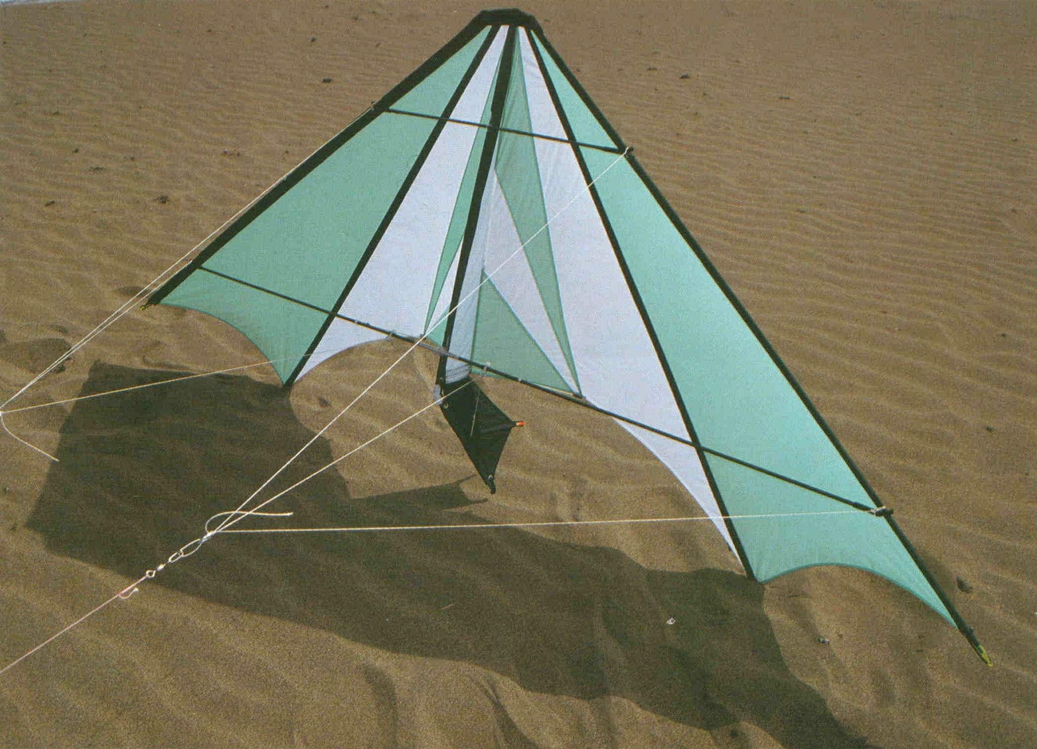
The kite presented here is a combination of the Garber and Rogallo kites. The surface of the keel guides the flow of air, which is transferred to the rudder. Semi-flexible sail surfaces provide good lift and allow for precise maneuvering. The kite is designed for flying in a fresh breeze and needs a 200-pound (100 kg) line.
Note: Avoid inhaling the dust you will create when cutting graphite or fiberglass-reinforced rods or the fumes from working with a hot-cutter or soldering gun.
Start by cutting out all twelve sections of the sail (A). Take note of the curved trailing edges, as well as the slightly curved edges of sections 4 and 5. First sew together sections 1,2, and 3. Then proceed to sew section 4 to section 1. The seams are on the back. Now, sew section 4 to section 5 in such a way that the seam is in front. Follow these steps for both halves of the sail.
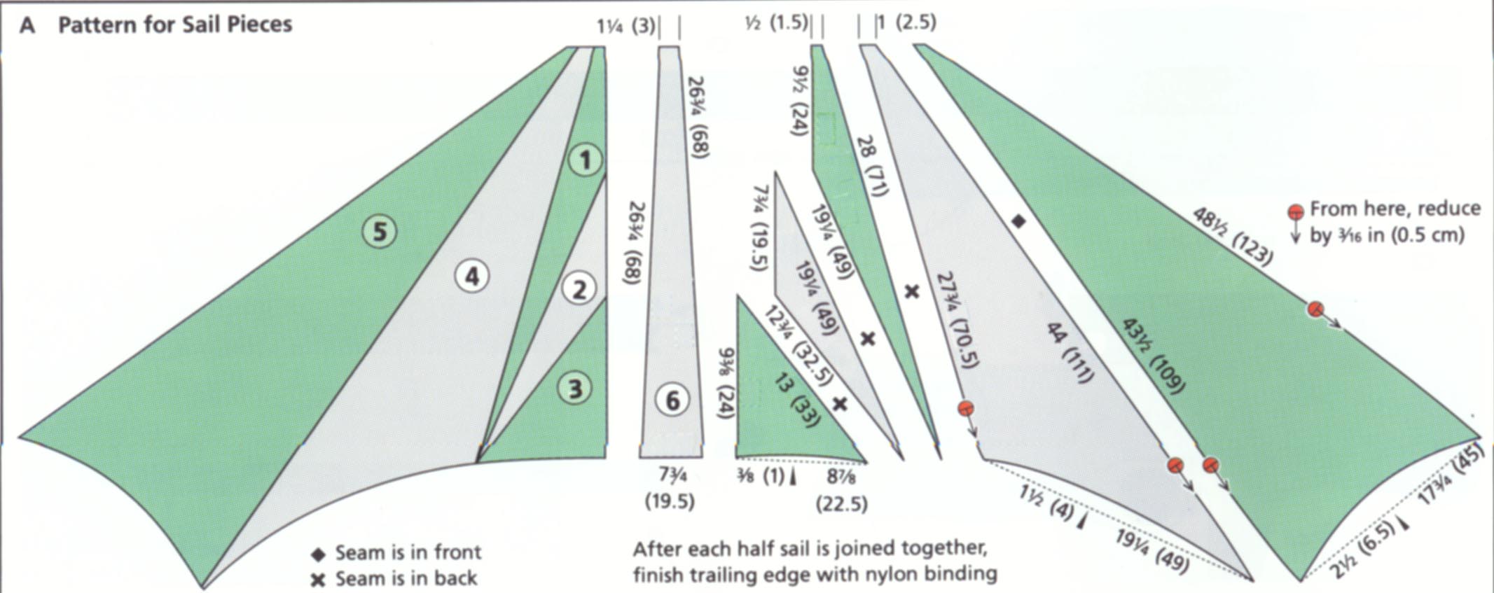
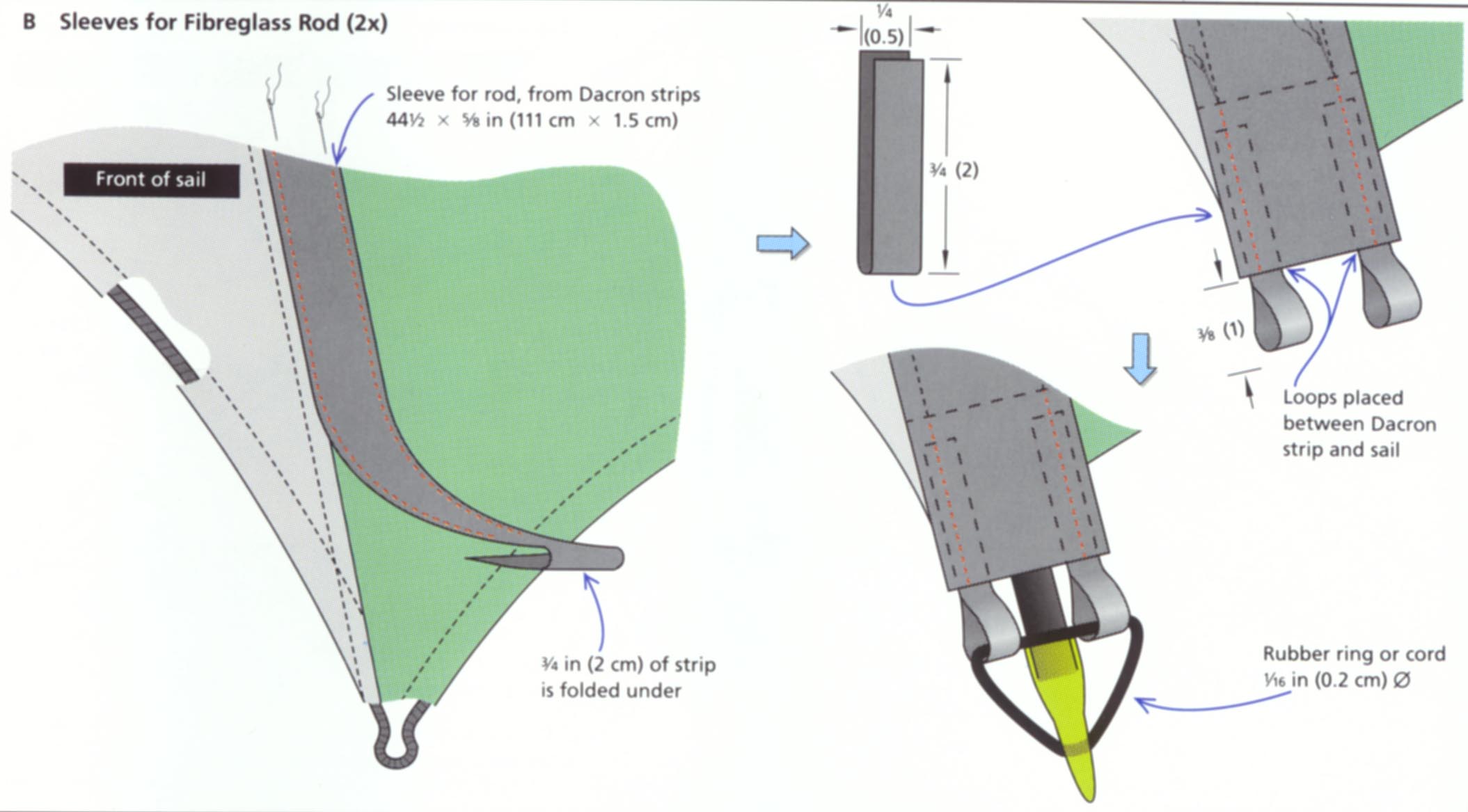
In order to prevent excessive fluttering of the trailing edge, finish the hem with Dacron tape. Make sure that the seam is in the back. Stitch a 5/8-inch-wide (1.5 cm) Dacron strip over the seams of sections 4 and 5; they serve as sleeves for the fiberglass rods. Prepare a strip 44½ inches (111 cm) long and stitch it to both halves of the sail as shown in diagram B. At the heel, the material is folded over to the inside; two loops, 2 inches (5 cm) wide, are sewn into the Dacron strip (B). The loops should extend about 3/8 inch (1 cm) beyond the sleeve. The end of the sleeve is flush with the hem of the trailing edge. Next, stitch the sleeve for the fiberglass rod in sandwich fashion at the outside edge of the sail (C). For this, you need to prepare a 48½-inch-long (121 cm) Dacron strip, 2 inches (5 cm) wide. Fold the strip in half lengthwise. Start at the tip and use the zigzag stitch. Place the sail 3/8 inch (1 cm) deep into the Dacron sleeve and stitch (C2). On the bottom, fold 1¼ inch (3 cm) of the material under and stitch carefully (several times back and forth) Do the same with the other half of the sail.
The keel is made from section 6 (sec A). First, make a double hem on the short end. Then, fold the nylon lengthwise in half (D). The center bar sleeve. like the side-bar sleeve, is made from a 2-inch-wide (5 cm) Dacron strip. The Dacron is also folded in half lengthwise and placed over the folded nylon piece, overlapping by 3/8 inch (1 cm) (D). Now. the Dacron sleeve and the nylon are sewn together, using the zigzag stitch (D). For extra strength, the Dacron material is folded double at the end. Be absolutely sure that the Dacron sleeve is flush with the hem of the trailing edge.
Now, join the keel sleeve and both halves of the sail. Place the sleeve between both halves (F). If this proves difficult, you can do it in two steps:
With a hot gun, make two holes 3/16 inch (0.5 cm) dia. in the reinforced ends of each of the end and side-bar sleeves. Attach a 3/16 (0.5 cm) dia. grommet in each hole (see diagrams C and I). Also, using the hot gun or cutter, remove a section in the center and side-bar sleeve for the T- and cross connector. Measurements are listed in the sail pattern diagram and sketch 1). Make sure that you do not inhale the vapors created when hotcutting the Dacron material; it is hazardous.
The nose of the Scanner is reinforced with a layer of Dacron as well as a piece of waistband; see diagram F. First put the Dacron over the front edge. The material in the vicinity of the center bar must become slightly domed. Stitch along the side center and fiberglass rod sleeve (see sketch F). Excess material is carefully cut off, making sure that the sleeves are not damaged. Now, fold the waistband lengthwise down the middle, place it also over the Dacron, and stitch everything together very carefully. Stitch another seam close to the side-bar sleeve. Excess waistband is also cut off.
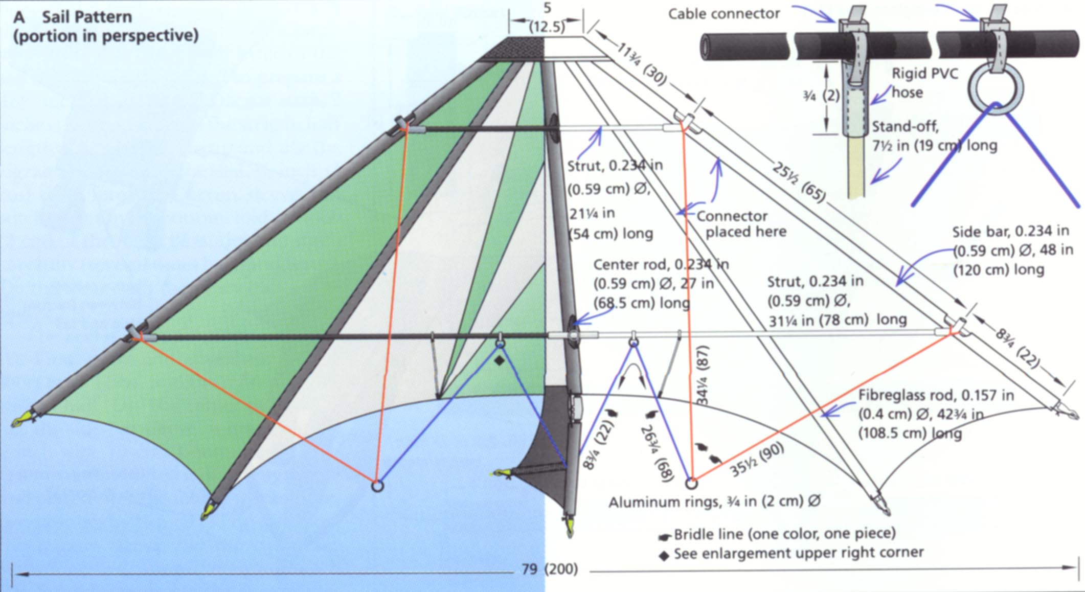
Next, make the four T-connectors, using ¼-inch (0.6 cm) inside dia. hose, and a cross connector, using 1-3/16-inch-long (3 cm) high-pressure hose with ¼ inch (0.6 cm) inside dia.. Cut a graphite rod, 0.234 inch (0.59 cm) dia., in half. Connect both pieces to a graphite rod, 32½ inches (82.5 cm) long and 0.234 inch (0.59 cm) dia., using aluminum tubes. Slide both side bars into their respective sleeves. T-connectors are placed at the cut-offs (see also sail pattern). Some pressure is necessary to push the hose through the tube.

Place both sail rods, 28½ inches (72.5 cm) long and 0.157 inch (0.4 cm) dia., into their respective sleeves. Like the side bars, the sail rods consist of one and a half pieces, but they are joined at their blunt ends. Arrow nocks are placed at each end and the fiberglass bar is secured with elastic cord.
Next, slide the center bar, consisting of a graphite rod 27 inches (68.5 cm) long and 0.213 inch (0.54 cm) dia., into the sleeve. The cross connector is placed at the cut-off, which is made from high-pressure hose (H).
Now, make the front strut using a graphite rod 0.213 inch (0.54 cm) in dia.. The rear strut, graphite rod 0.234 inch (0.59 cm) dia., consists of two equally long pieces (see sail pattern). They are pushed into the T-connector as well as in the 3¼-inch-long (8 cm) aluminum connector. This aluminum connector, preferably, should have a center bar to prevent the struts from moving. If there is no center bar, you must provide both strut bars with a sufficiently thick layer of fiberglass-reinforced tape about 1½ inches (4 cm) from the ends.
Both stand-offs are made from fiberglass rods 0.118 inch (0.3 cm) dia.. At the trailing edge of the left and right half of the sail each, attach a vinyl cap 1/8 inch (0.3 cm) inside dia. fastened into place with a narrow cable fastener. Punch a hole with the fine tip of a hot gun into the right and left trailing edges -- making sure that the seam is not damaged. The positions of the holes are between parts 1 and 4 (see drawing A). Punch a hole 3/32 inch (0.2 cm) dia. into the very end of the end caps and fasten them to the trailing edge with the cable fastener that must be guided around the Dacron reinforcement.
The stand-offs at the rear struts are placed into rigid PVC-hose, 0.118 inch (0.3 cm) inside dia.. Holes are punched at the very end of the 3/4-inch-long (2 cm) hose and fastened to the strut with cable fastener (see sail pattern). It is recommended that you place adhesive tape under the cable fastener to prevent it from sliding. Position the 7½- inch-long (19 cm) rod into the support.
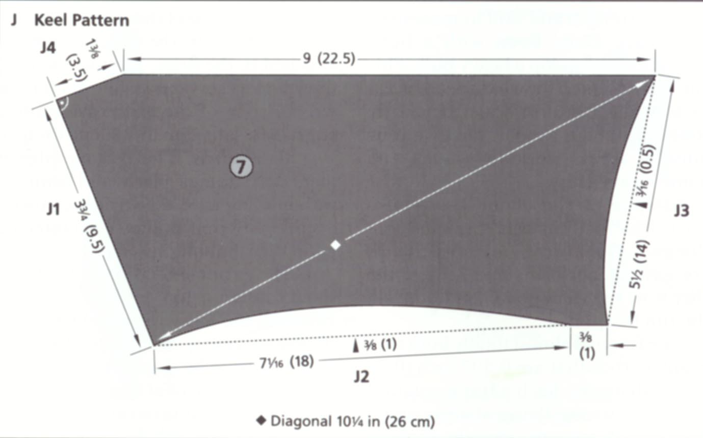
If you want to use the Scanner without a keel, you must secure the center bar with an arrow nock and elastic cord. The bridle is not guided through the ring to the keel but rather attached to the center cross (see sail pattern). If, however, the kite is to be used with a keel, you must stitch a strip of Velcro tape about 3/4 inches (2 cm) long along the rear edge of the keel. Cut out the keel (section 7) according to drawing J. Edges J1 and J2 are hemmed with a double seam. Carefully stitch a 3/4-inch-wide (2 cm) felt strip to edge Jl. Following diagram I, stitch a 3/4-inch-wide (2 cm) piece of Dacron to one side of the sail, folding it over before sewing it in place, and you will have made a loop.
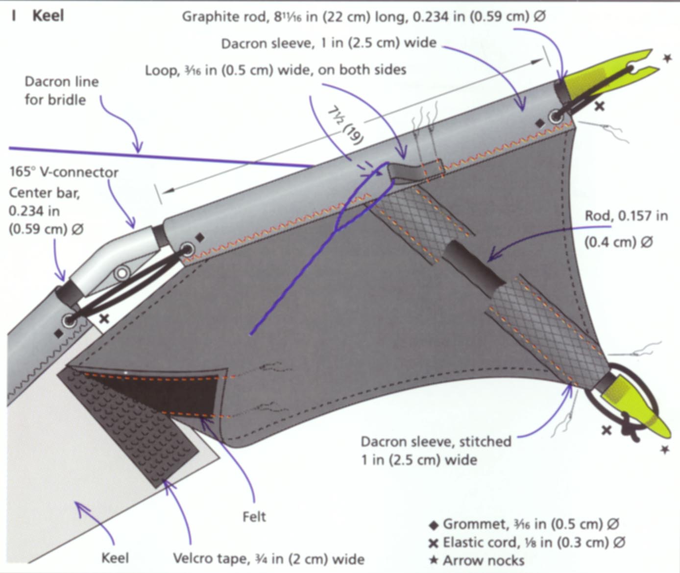
The hemmed edge serves as a sleeve: fold a 2-inch-wide (5 cm) piece of Dacron, sewing it -- —as already demonstrated -- to the keel in sandwich fashion. For reinforcement, fold 2 inches (5 cm) of the material under at each end. Leave the seam open where the pocket slides under the Dacron sleeve (I). Next, stitch two small loops of 2-inch-wide (5 cm) tape to the left and right from the sleeve (I).
Fasten two grommets at the end of the Dacron sleeve of the keel. Slide a graphite rod, 8-5/8 inch (22 cm) long and 7/32 inches (0.54 cm) in dia., into the sleeve and connect it to the 165° V-connector of the center bar. Two rubber bands will stretch the sail. One rod, 0.157 inch (0.4 cm) dia., with an arrow nock and elastic cord stretches the keel to the back (I). Push the Velcro together securely to tighten the sail of the rudder. Attach the bridle line as instructed on the sail pattern. A line, running to the center bar, is attached to the left and right to the keel. Two aluminum rings are used to attach the bridle line and to change the angle of inclination.
 By permission of Wolfgang Schimmelpfennig, from his book Making & Flying
Stunt Kites and Other One-Liners, (English edition: Sterling Publishing, 1995;
German edition Neue Lenkdrachen und Einleiner bauen und fliegen, Falken Verlag, 1993).
By permission of Wolfgang Schimmelpfennig, from his book Making & Flying
Stunt Kites and Other One-Liners, (English edition: Sterling Publishing, 1995;
German edition Neue Lenkdrachen und Einleiner bauen und fliegen, Falken Verlag, 1993).
He has written a number of books about kites, both single-line and stunt kites. He is also one of the founders of the "International Kiteflyers Meeting" at Fano in Denmark. The year 2005 will be it's 20th anniversary. Each year it attracts thousands of kiteflyers from around the world. ... and special thanks to Detlief Griese for finding these plans and assisting in contacting Wolfgang! |