Although I'm writing this article in 2005, the rig I'm describing was made in June of 2003. It is a direct follow-on to my "Rig #1", incorporating several improvements. In particular, extensive usage of my first rig revealed several deficiencies:
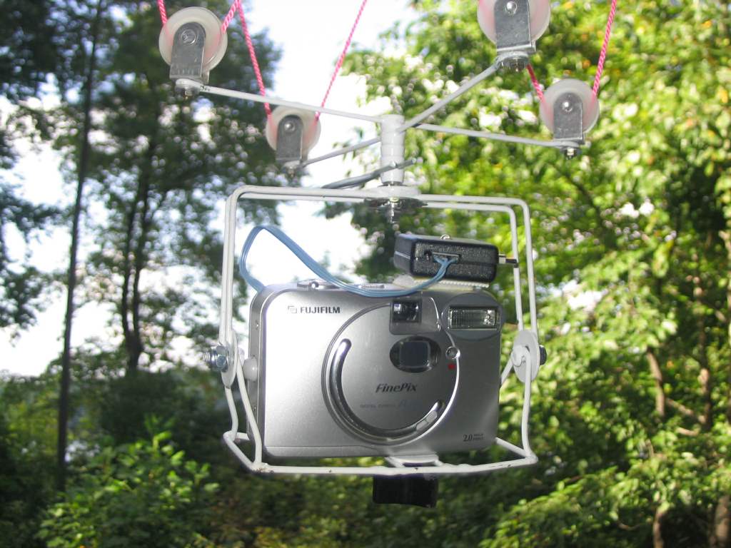
My new rig overcomes these objections, while still being of the same general construction. Here's a photo of it with my rugged Fujifilm camera.
Again, I used a steel wire similar to coat hanger wire. It's actually sold as something to hold insulation up under floors. I used a small tank of MAPP gas with a suitable MAPP gas nozzle to braze the wire together. The brazing wire and MAPP gas are available in most hardware stores these days. I would imagine you could get away with solder, but I don't know for sure.
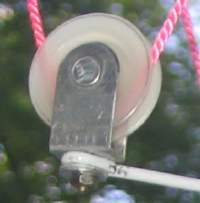 For pulleys, I found some cheap nylon rollers in the screen door repair area of my local
Lowe's. I had tried to do some "scientific" tests on these before and the results looked
promising. (You can see the results here.)
For pulleys, I found some cheap nylon rollers in the screen door repair area of my local
Lowe's. I had tried to do some "scientific" tests on these before and the results looked
promising. (You can see the results here.)
They're a little tricky to detach from the mounting strap, but they're very cheap and light. The clearances are such that the string can come off the pulley and get caught between it and the frame, but I've never had this happen in the air. I also mounted them so the rig could be set up for Picavet or Rendsburg by just rotating the pulleys.
The doubled-up wire frame has been more than strong enough, and extends enough out in front of the camera to protect it from most landing problems. At the center of the suspension cross-members is a brass fitting with a hole in it (found in the plumbing department). The camera holder has a 1/4" metal shaft which projects up into the hole and is secured with a removable pin. I had hoped to make it more portable by having the rig and camera easily detachable, but I haven't made much use of this feature.
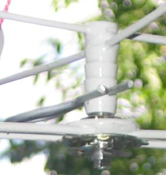 Another innovation that has worked out is the attachment of the camera holder to the rig.
That 1/4" shaft projecting from the top of holder is part of a rotary switch from Radio
Shack. It has spring loaded detents so it will let the lower part of the rig turn to any
of several positions, and hold it there. The electrical components of the switch were
discarded.
Another innovation that has worked out is the attachment of the camera holder to the rig.
That 1/4" shaft projecting from the top of holder is part of a rotary switch from Radio
Shack. It has spring loaded detents so it will let the lower part of the rig turn to any
of several positions, and hold it there. The electrical components of the switch were
discarded.
My last innovation was to substitute an all-electronic solution to triggering rather
than using a relay like Rig #1. The schematic is shown below.
The drawback to this new scheme is that the camera is not 100% isolated from the
trigger circuit, and you can tell this by a dim glow on the trigger module LED. But
it has not proven to be a problem. The real problem is the tiny circuitry in these
modern cameras. It's very risky to open one up and start soldering. Also, note that
unlike the relay version the connection to the shutter switch will vary depending
on your camera's circuitry. As I recall, the effect of this circuit is to "ground"
one side of the shutter switch, causing it to take a photo. Check to see if one
side of your shutter switch is a ground, and attach this circuit to the other side.
|
|
So that's my improved KAP rig. My next rig will have either some sort of radio or pre-programmed camera controller. I want the camera to at least turn while the kite is airborne, without my having to pull it back down. With a manual rig like this, it takes a lot of flights to get one really good photo.
