


The difference between "Measuring" and "Lofting" is apparently that lofting is the process of turning the data collected into a working drawing of the station and not the actual collection of the data. Since the Lofting station actually "measures" data (2) and also "Lofts" data (3), the name might be misleading, but hopefully this is cleared up now.
In this sample, I measured Cross Section data from BIF-16, a single chine K-1. I did only one station (Station 5). I measured the keel, chine, and gunwale, but could have captured deckridge data also.
It can't be that easy!
Yes, it's amazing how simple, seemingly complicated processes can be. I came up with this solution over 20 years ago when I had access to a friends Jensen Pro Boat (Racing Canoe). I tried bending soft aluminum tubing around the sections, cutting and pasting construction paper, and even fiberglassing nylon rope before finally "seeing" this solution. Sometimes you just need to step back and look at things from a different angle. For all I know, there could be others "measuring" this way, but I've never seen it done.
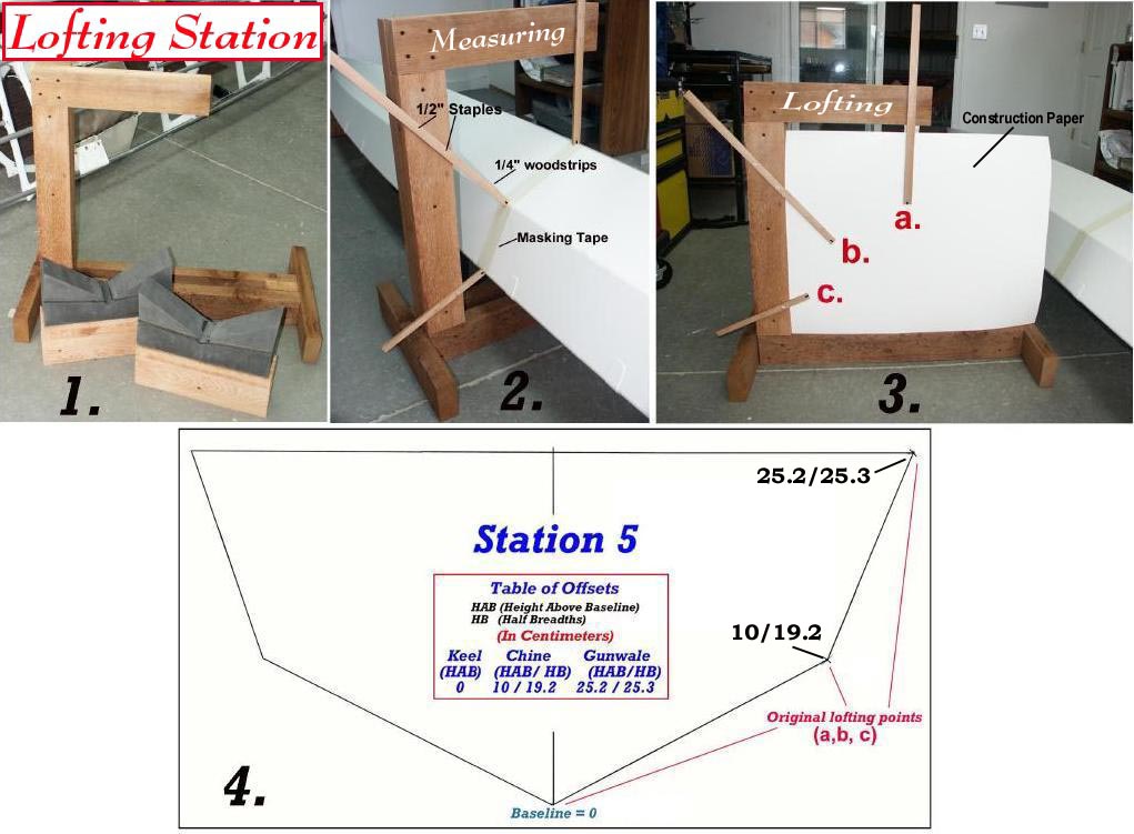
1. Lofting Station It is used to capture data (2) from one side of the hull/deck. The captured data is then used to define both sides of the station. If required, the Lofting Station could easily be moved to the other side of the station to measure that data also. In addition, the Lofting Station is used to loft measured data (3) directly to a full-sized working drawing. Another reason for the one sided design is to allow it's removal without disturbing the kayak. You will also note that the cradles for the boat are on stands that are higher than the base of the Lofting Station. This insures that the Lofting Station can move freely along the boat.
2. Measuring Masking tape is used to mark off the station being measured . I'm using only one for this sample, but in practice I captured data every 1.5 or 2 ft. Woodstrips (1/4") are attached to the Lofting Station with 1/2" staples. This length staple holds the woodstrip strip firmly but also permits easy removal. When done with a station, simply pull off the woodstrip/staples and reposition at the next station. Replace staples when needed.
Mark the end of each strip to indicate the point of contact. Slide the Lofting Station under the deck and align woodstrip (A) with the Keel (touching). Once aligned with the keel center, staple the strip to the frame. You could use a pointed strip but it really makes little difference as long as the strip is marked. Do the same for the Chine (B) and Gunwale (C). Once this is done, repeat this procedure with the Chine (B) and Gunwale (C). Next, slide the frame out from under the boat and begin the lofting process.
3. Lofting - "To lay out a full-sized working drawing of the lines and contours of (as a ships hull)."
Tape a sheet of construction paper on the Lofting Station as shown in the photo. In the past, I used a sheet of plywood equal in size to the construction paper to add rigidity. For this sample, the paper alone will suffice. Place marks on the paper to indicate the Keel, Chine, and Gunwale contact points. Once done, move to the next station and do it all again. Be sure to indicate which marks go with what station, or simply use a different sheet of construction paper for each station.
4. Lofting (cont.) Once all stations are measured and marked, place the construction paper on a flat surface/table and use a T-Square to draw line indicating the top of the station at the Gunwale (c), and another one indicating the centerline of the station at the keel (a). Draw a line between the marks for the keel and chine , and the chine and gunwale. For this sample, the "Station 5" keel represents the baseline ( lowest point of keel) although in reality, the baseline may be at a different station. You can now create a complete cross - section if desired by duplicating your results on the other half of the center line.
Since I like to use a "Table Of Offsets", I also record the Height Above Baseline (HAB) and Half Breadth (HB) data. The cross-section drawing in figure 4 displays both the lofted section and it's corresponding Table of Offsets.
Contributors to this page: Thomas Yost (TDY), Patrick Poirier (PPR), Gerald Maroske (GUM) and Hendrik Maroske (HHM)