


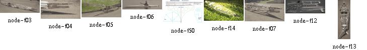
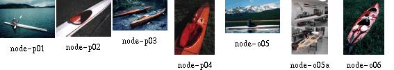
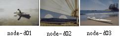
Aircraft Transportation: how to paddle an aircraft... This picture belongs to the Northwest Territories' Photo Database. They have 82 inuit kayak photos, which you can find by entering 'kayak' as the search item.
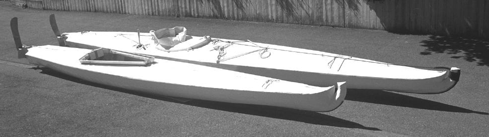
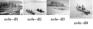
George Dyson´s ''Mount Fairweather'' baidarka was launched in June 1975 at Vancouver City and some days later made its way up to northeast Vancouver Island. The summer solstice of 1995, nearly exactly 20 years later, my brother Gerald and I enjoyed a trip to the Discovery Islands. This trip also was a test of my brother's newly built folding Greenland Eskimo Kayak.
We crossed paths with George Dyson's and similar expeditions. In part, that trip was a sort of a ''dream-come-true''; inspired by our reading and re-reading of George's and Kenneth Brower's books.
Compare the characteristics of our kayaks and let me point out these inspiring journeys, so much more than what we have achieved:


Take care.
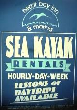
We reached the starting point after riding the ''Victoria Clipper'' from Seattle; there is a bus to Campbell River via Nanaimo. We took several taxis and the Quadra Island Ferry; but the afternoon ''Clipper'' from Vancouver was too late for the Quadra ferry. If you take one of the morning sailings, you get to Heriot Bay within one day. At Campbell River, the local ''Tonys Taxi'' moved us around on Quadra Island. You can rent a kayak at Heriot Bay; so our effort of boatbuilding saved us 180 dollars for a rental kayak:
We move easily, unafraid of what lies below because we ourselves have created above. Our craft forged by our hands, dreamed into existence by our hearts.
This is why we are here. This is who we are.
This wildness. This earth.
These hands. This heart.
This life.
My life.
Unfolding across the infinite span of creation and experience.
Earth, hands and heart pulsating in unison."
Contributed by Ken Lalonde
Edmonton; Alberta, Canada
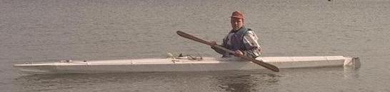
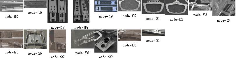
Barnackles and rocks are no problem for these boats. More likely the Surge Narrows, through which we will pass. Maximum current 9 knots. Compare the really large rudder with the small one of my new design, which is still more efficient because the new boat handles a lot better.
We came at the time of maximum currents at the narrows. From someone at Campbell, we learned that in our trip's area were currents of ''40 knots, and whirlpools to the ground''. Although that surely is an exaggeration, we had a lengthy discussion before we entered Surge Narrows; we sat on the small Welsford Island and began interpreting every written word...
The area around Maurelle Island is described in John Ince's well known book ''Sea Kayaking Canada's West Coast''; but since then, the shop at the Surge Narrows Community seems to have been closed a long time. We had sort of a surprise, the day we wanted to take up provisions there. The surprise consisted of a long paddle without breakfast. In contrast to that, the village at Heriot Bay has precise charts, food, camping and everything. Another notable change might be the forest. I don't know how it looked in those times; but today there is a lot of second-growth forest. It is in a good shape, so we realized the fact only after a while. But this resulted in a reduced population of animals. Except of a lot of ravens, we were a bit lonely in those places. We even did not see any raccoons.
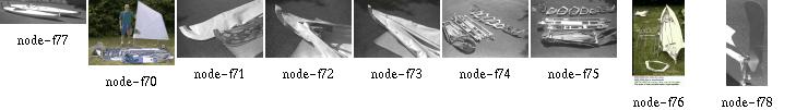
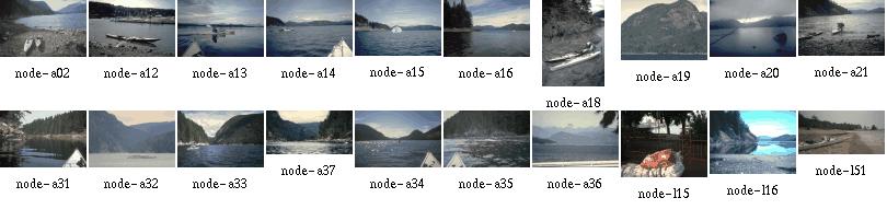
In fact, this day started as a perfect day for
fishing, like many other days.
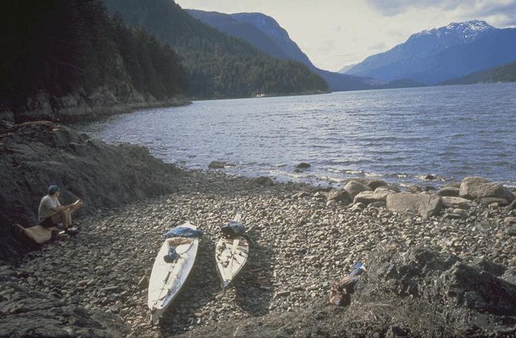
Here, we are landing in search for a camp site. To learn more about our camping, click here.
Realize that the water is already on the move. We didn't and had a somewhat interesting experience right after the narrowest part. It was like someone lift the stop of a huge bathtub...
Here's a map:
And here a flight simulator view from above:
This slide show is about baidarkas. But with a bias towards folding boats and Greenland style kayaks. ''Baidarka'' is a russian word for ''small boat'' which got used not only for Aleut kayaks but especially for Kodiak kayaks which differ noticeably in construction.
This project was initiated by George Dyson's book ''Baidarka''. I consider George Dyson´s three-man kodiak baidarkas to be his most inspiring work, together with the part of the book that treats their history.
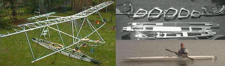
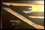
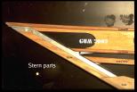
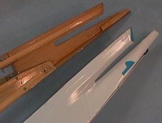
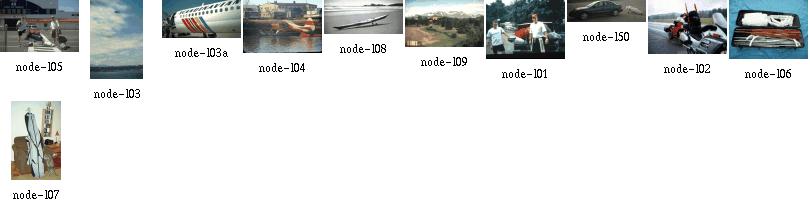
But what got me started into the Baidarka thing in the first place, is the nice connection he made between Boeing aircraft, aluminum tubing, scrap yards and modern Baidarkas. That's why I chose the pic with the airframe and baidarka for this page; my interpretation of the theme has always an aircraft bias towards it. If I cannot build an aircraft due to the huge amount of time, money and experience necessary, the next best thing to build is a Baidarka. I took up the construction of five baidarkas as a means of gaining experience for making an aircraft. Especially the three folders helped in learning to take matters more seriously. It seems that others share the same motivation, for an example take a look here, Or take a look at Geralds kayak parts, although maybe not intentionally, they somewhat look like airplane parts as well. My own construcion in comparison somewhat looks like a tank or gun (better than the furniture I made, it all looks like coffins), and the construction was nearly as much effort as a assembling a small airplane kit.
Also, with a folding kayak, I was depending upon airlines a few times for transportation. This is a good place to return the favor I received from the friendly folks there.
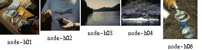
These pages also contain travel pics, shown from the perspective of someone carrying around 120 to 140 pounds of gear per person...
Interested?
Here is more about my BUG2 (acutally named BUG2-2).
Skin-on-frame airplanes...
Spars were 2in aluminum tubing with 0.024in wall thickness, reduced by chemical milling to 0.016in for the outer wing. Talk about optimization...
There is more info on Paul Mc Cready's web site.
Cited from Paul's web site:
It demonstrates what
can be done with low power, when new concepts of efficiency are unleashed
by challenges not burdened by constraints from narrow rules or the need
for commercial production.
We move easily, unafraid of what lies below because we ourselves have created above. Our craft forged by our hands, dreamed into existence by our hearts.
This is why we are here. This is who we are.
This wildness. This earth.
These hands. This heart.
This life.
My life.
Unfolding across the infinite span of creation and experience.
Earth, hands and heart pulsating in unison.
Contributed by Ken Lalonde
Edmonton; Alberta, Canada
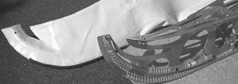
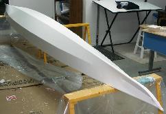
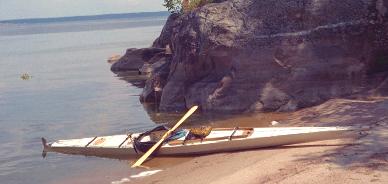
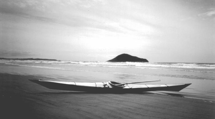
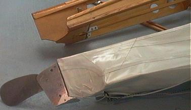
People often ask me that question, and I still have nothing useful to throw at them as a one-shot answer. Especially because it only makes a lot of work. But that bow is an important part of the picture I had in the very first place after reading George Dyson's book: I saw myself sailing an aluminum Baidarka along some part of the Inside Passage. What kept me going full power through all these years was that picture. Then a lot of help from my brother Gerald made it come true; he also took the right photo at the right time, and now it occupies some 2x3 foot on my workshop wall...
Skin-on-frame airplanes...
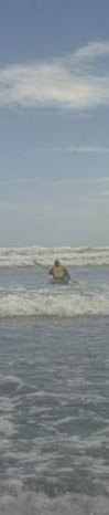
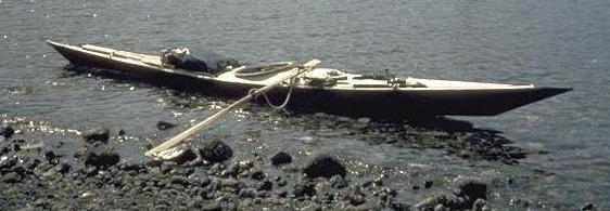
But what started me into the whole paddling business was this Oregon Coast trip in 1992.
This slide show is about Baidarkas. But with a bias towards folding boats and Greenland style kayaks. ''Baidarka'' is a russian word for ''small boat'' which got used not only for Aleut kayaks but especially for Kodiak kayaks which differ noticeably in construction.
This project was initiated by George Dyson's book ''Baidarka''. I consider George Dyson´s three-man kodiak Baidarkas to be his most inspiring work, together with the part of the book that treats their history.
But what got me started into the Baidarka thing in the first place, is the nice connection he made between Boeing aircraft, aluminum tubing, scrap yards and modern Baidarkas. That's why I chose the pic with the airframe and Baidarka for this page; my interpretation of the theme has always an aircraft bias towards it. If I cannot build an aircraft due to the huge amount of time, money and experience necessary, the next best thing to build is a Baidarka. I took up the construction of five Baidarkas as a means of gaining experience for making an aircraft. Especially the three folders helped in learning to take matters more seriously.
It seems that others share the same motivation, for an example take a look here, Or take a look at Geralds kayak parts, although maybe not intentionally, they somewhat look like airplane parts as well. My own construcion in comparison somewhat looks like a tank or gun (better than the furniture I made, it all looks like coffins), and the construction was nearly as much effort as a assembling a small airplane kit.
Also, with a folding kayak, I was depending upon airlines a few times for transportation. This is a good place to return the favor I received from the friendly folks there.
These pages also contain travel pics, shown from the perspective of someone carrying around 120 to 140 pounds of gear per person...
When you take it apart does it become a kit?
Well, yes. My first designs took several hours to assemble. Now I am somewhere at under an hour assembly time. But basically, my folding Greenland Baidarka still is somewhat of a construction kit.
But that is no real problem. My own design assembles a lot better than the two-place folder I have bought. Joints are a lot more precise and rigid, and the overall stability of my frame is worlds apart from that of the commercial product. So it definitely is worth the extra effort at assembling the Baidarka. At least, there is no commercially available folding Baidarka, and I think I know why. I designed my foldables against the structural strength of a rigid Baidarka. Problem is, I only have had two rigid aluminum designs of my own deviation from George Dyson's. This deviation makes it difficult to give absolute numbers.
Here is more on frame stiffness measurements.
Now that I have made a wooden foldable Baidarka, I can tell that my very first aluminum designs were a lot less flexible than this wooden version. This was due to my usage of tubing with very large outside diameter (20mm). Using 18mm tubing should give better results. Using thin-walled tubing will have the problem associated with it that during transport the tubes will get bent and dented.
Anyway. The Aleuts fixed their gunwales into the stem and stern deadwood and made sure they would not move within these joints. Gerald and I simply kept to this rule and made sure that all the foldable longitudinals are thoroughly interlocked to prevent them from changing their length, no matter how thick or thin they are. This was a major design problem for us since anything that interlocks is an attraction spot for salt water. This tends to transform a folder into a partly rigid boat that defends itself from being disassembled (as mentioned in Gerald's "bloody fingers" mail).
And don't forget the skin. A good part of the stiffness of the boat is due to the tension of the skin - it limits the motion of loosely assembled parts.
In this my first folding design, a very loosely fitting skin was laced over a very loose frame. One could forget about the skin's contribution to frame stability; in my case, this worked only in theory. Maybe this is due to actually very small loads, I don't know. Here are measurements that seem to point in the same direction.
However, some parts of that frame were put loosely together for my inability to do a better design. Some parts even had some sort of interlock that I had to cut away to be able to assemble the boat. In essence, being outdoors gave nature a great chance to get me streamlining my assembly procedure.
But it was amazing what loads and abuse that frame was able to bear. This surely is good news for any newcomer. At least in my case even that first design was well good enough to do the job.
Some of the slides are large animated GIF movies. To reduce load time I have cut the assembly process into parts. Just keep in mind that the assembly happens within the skin, but is shown without the skin for clearance.
This whole shebang is available on a CDROM, including several other web sites. It is made by Charles Hall and distributed for production cost.
The animated assembly movies of LostSoul:
With this design I wanted to reduce the height of the deck stringers. I always wondered if the one-hatch Baidarka deck design really is the big thing, partly because I am making foldable Baidarkas:
Surely the Aleut people had their ways to cope with that, but I was struggling to make my craft seaworthy. According to today's accepted safety standards. I had to change it in order to get a foldable design, and the result is very similar to the Greenlanders, especially since the waterlines of my folding kayaks come close anyway.
Well, this looks like something. I made a good rear hatch, with the pump installed and everything, skipped that rear deck stringer and now have a nicely fitting tilted cockpit. Seems like progress.
Here is what others have said about my modifications to the Aleut design.
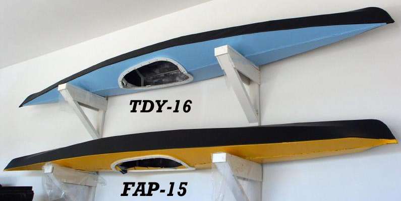
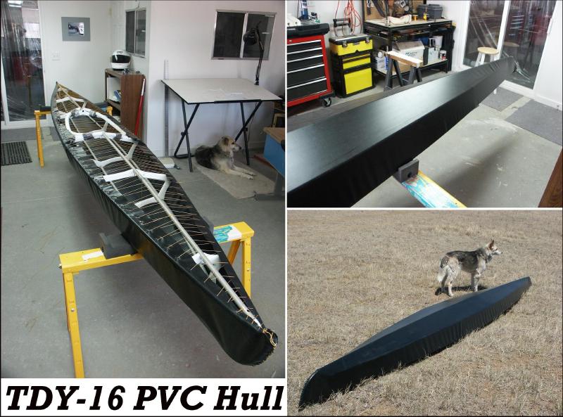
In order to save weight, TDY-16 is built using 3/4in X 0.035 tubing. In addition, there are 6 HDPE cross sections (FAP-16 has seven). The HDPE stem/stern use lightening holes, and the coaming will be light weight fiberglass. The frame, without coaming, weighs 13.5lbs. Completed weight with 13oz. PVC skin material should be approx. 25 lbs.
LOA - 16ft.
Beam - 23in.
Weight - 25 lbs.
Stringers - Aluminum 3/4in. X .035 Walls
Skin - PVC
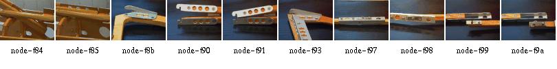
This Non-Aleut design is intended as a lightweight medium volume touring kayak. As compared to FAP-16, it features a peaked deck to improve interior room for the paddler as well as more storage space. It utilizes thinner walled tubing (3/4" X .035) and six cross sections ( FAP-16 has seven) to reduce weight. The cross sections, coaming, and footbrace are made from HDPE. Finished weight is approx. 26 lbs.
The skin is a sewn, one-piece Polyester (9 oz.) design, and is coated with Neoprene/Hypalon. The hull is covered with eight coats of neoprene, while the deck is covered with five coats neoprene and three coats Hypalon. Neoprene is a bit easier to apply than Hypalon. It cures quicker, and is more durable. Hypalon has the advantage of being easier to fold, and is available in many different colors.
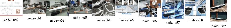
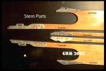
The following pages highlight only those construction details not included with, or that differ from FAP-16:
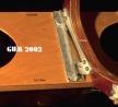
Stem, Stern and Frame
FAP-16 and TDY-16 Frames
TDY-16 Frame
Coaming Details
The HDPE coaming is comprised of 1/4" baseplate, 1/2" coaming, and 1/8" coaming lip.
Machine screws are used to provide a secure coaming attachment.
Polyester Skin (9oz.)
The one-piece Polyester skin is sewn with nylon squidding line.
The deckridge and stem/stern are cut (seared)
with a propane cutting blade prior to sewing. This process
assures a hard edge that will not separate.
The deckridge will be cut open for the installation of lacing or zippers.
Neoprene
The frame is first waxed to insure that neoprene will
not soak through and stick to either the aluminum or HDPE.
Before coating , a heat gun is used to remove wrinkles
still remaining in the skin after sewing.
The first two coats of Neoprene are thinned with 10percent
Zylene to insure that the neoprene will soak deeply
into the polyester cloth. Subsequent coats are thinned
but to a lesser degree.
Neoprene is applied with a 3 or 4 inch brush. Use short brush strokes and be sure not to brush the neoprene once it starts to glaze over. That will cause ripples in the surface. Maintain a wet edge and move quickly along the surface. Subsequent coats of neoprene can be applied every 30 minutes or so.
When the skin is removed, the inside hull will receive 2 additional neoprene coats. This is not necessary, but will insure complete saturation, and makes for a better looking job.
Always wear a respirator, and work in a VERY well ventilated area.
Hypalon
After applying neoprene, the deck or hull can be coated with
additional Hypalon to give it a color other than black.
Hypalon cures slower than neoprene and requires a longer
wait between coats. Hypalon stays slightly tacky
for a few weeks. Adding Lacing, zippers, flaps, and deck
rigging can be done in a week or so after coating.
Wait several weeks after coating before removing the skin.
I normally wait a couple of months before folding the skin.
The main advantage of the Polyester/Neoprene/Hypalon skins are their one-piece construction and ease of repair. An additional coat of Neoprene/Hypalon every couple of years will keep it looking like new.
Rub strips can be glued to the keel and chines for added durability.
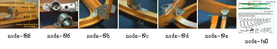
Skin/Coaming Attachment
On FAP-16, the skin to coaming attachment is accomplished
by wrapping the skin under the baseplate and using snap connectors
(see here for the idea).
On TDY-16, the skin is attached directly under the coaming with machine screws and recessed snap connectors. This is a cleaner installation, but the other method is easier.
Finish
At this stage, all that is left is to install lacing or
zippers, attach the flap, and deck rigging.
The seat is a gunwale mounted sling type similar to that
in FAP-16. A paddling report will be added later.
The cross sections, backrest and footbrace are made of HDPE. The skin is a sewn, one-piece Polyester design. Coating are Neoprene/Hypalon.
The deckridge is considerably taller than FAP-16 to provide greater room for comfort and storage. Personally, I prefer lower, flatter decks, but wanted to provide an alternative for other builders. This Aleut based frame is made of 5/8" tubing. Though flexible, it showed no signs of deflection in the water. The HDPE cross sections allow for ease of construction and assembly. The tubing size and number of cross sections are the same as the Feathercraft Kahuna (14'6" LOA). Tubing size can be changed to 3/4" if desired during construction.
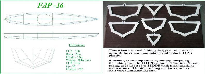
The design goals for FAP-16 were to make the kayak easy to build (Under 100 hrs.), Easy to Assemble (Under 30 Min.), and light weight (under 40lbs). Above all, Tom wanted this boat to perform as well as any non folding skin kayak.
LOA - 15ft. 8in.
Beam - 23in.
Weight - 35 lbs.
Stringers - Aluminum 3/4in. X .049 Walls
Skin - Polyester/Hypalon

LOA - 16ft 2in.
Beam - 20.5
Weight - 25lbs.
Construction Time - 75hrs.
Tom writes:
I've just recently completed a new kayak after a few years inactivity. The design is a hard-chine Iqyax (CNM-12212) that I built based on a simplified version of George Dyson's method utilizing aluminum stringers with plywood cross-sections. The skin is 8oz nylon coated with several coats of neoprene/hypalon.
Length - 17.5 ft
Width - 17.5 in
Weight - 28 lbs.
Cp - .61
Tom has built approximately 16 boats since 1975, with the first eight being woodstrip/fiberglass sea kayaks. Of that group, two have been Aleut designs constructed from David Zimmerly's offsets in his book "QAJAQ". He built them to scale but made changes to the deck shape. In addition, Tom built a woodstrip version of George Dysons double .
Having grown a bit tired of building woodstrips, he decided to try a hand at non folding skin boats. He first made three George Dyson singles, the first two of all wood construction, and the third using wood cross sections with aluminum stringers.
He immediately realized that these were more seaworthy than were the woodstrip hulls. The flex in the skin and the concave skin shape between stringers, really slowed down the roll rate as well as allowing the hull to conform to the waves.
The first folder that Tom has made, about 1993 or 94, is a folding wooden (pine) version of a Dyson single. Skin is Nylon/Neoprene/Hypalon. Time to assemble - Forever !
His second folder was an
Aluminum/Wood Dyson Double (1996).
Third was an Aluminum/Wood single (1997).
Fourth was an Aluminum/HDPE single- FAP-16(2002)
Fifth is an Aluminum/HDPE single - TDY-16(2002).
Sixth is an Aluminum/HDPE single - TDY-15(2002).
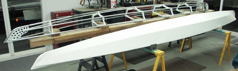
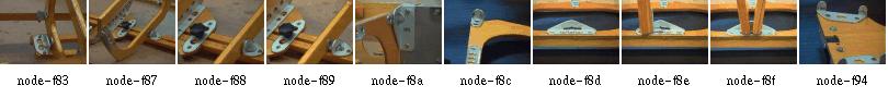
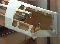
Above is a photo of the folding single that Tom was building 1998(?). You will notice a striking similarity to the "Feathercraft" designs. Since he paddles a Feathercraft K-Light, the similarity is no accident. You will also notice that there are very few parts. This boat follows the KISS principal. ( Keep It Simple Stupid)!
The tubing is all 3/4 in. Aluminum 6061/T6 thin wall. The tubes are attached to the Cross sections using "L" shaped brackets pop riveted to the tubes. The frame weighs about 15 lbs and takes only a few minutes to assemble. The frame has a single stretcher bar at the keel. The skin will be made of 14 oz. pre-shrunk nylon. The material will be coated inside and out with three coats of black Neoprene. The deck will receive additional coats of white hypalon to provide a light color. The boat is 15.5 ft (4.73m) long by 24 in. (61cm) wide.
Tom plans to use zippers along the deck ridge for closure and sewn in sponsons to assure a tight fit and to provide additional stability.
At least in my case, the zipper/sponsons solution has worked more than once. Just take care.
They keep getting lighter, easier to build, and quicker to assemble.
The frame contains four sections which are joined by metal joints.

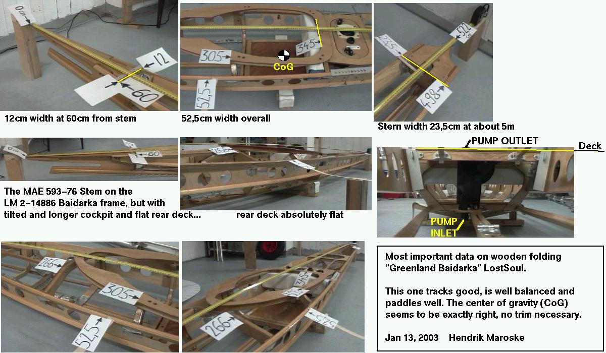
Total length of the kayak is 5.35m and width is 52cm. It weighs 20kg.
The fore and aft sections are assembled separately. The two middle frames are inserted after stringers and keel are joined inside the hull.
The frames are made of seven-layered, nine millimeter birch plywood except the two main
frames in the middle, which are doubled to 18mm.
The massive parts are all ash and the gunwales/1st chines
are stiffened by 3mm 6-layered birch
plywood.
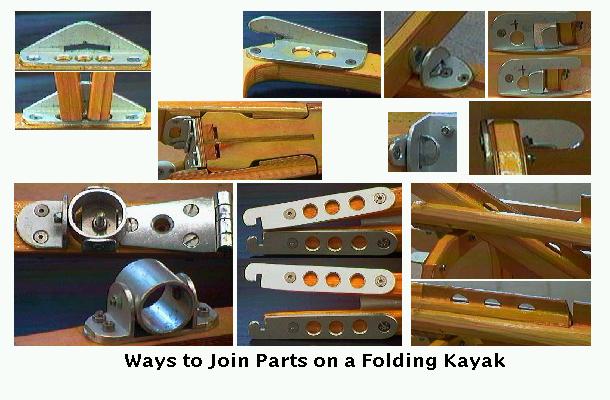
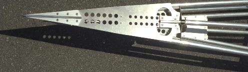
The joints are made of aluminium and stainless steel parts and all screws are made of stainless steel. Most nuts used are selflocked. All joints are handmade. The joints for the keel and the joints separating the fore and aft sections are tightened by hexagon screws. All other joints are assembled without tools.
The skin is polyester-reinforced-PVC (truck cover) for the hull and cotton/polyester for the deck. The hull is made of 3 parts each side (~36m to sew) but the deck is one piece. The inside of the deck is sealed with a layer of silicone (used for sealing windows etc.).
Assembling starts with the rear section inserted first. This is done because the cockpit coaming is installed with an angle, which provides a better in and out and this is valid both for paddler and framework. A special tightener is used to pull the keelparts apart and stretch the skin. When the keel is joined, both gunwale-joints are also pulled apart one-by-one and joined. The stringers are now joined easily. The last two frames are inserted starting with frame No.4 (backrest) and then No.3 (kneeframe or masik). When this is done the deck stringers are inserted and the last thing is to attach is the cockpit-coaming (steam-bent out of two parts, lip and ring are both ash of 1cm thickness, for a procedure look at Chris Cunningham's article "Building a greenland kayak" in the 'Seakayaker' magazine).
Assembly time is 35 minutes for me (Gerald).
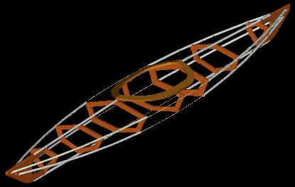
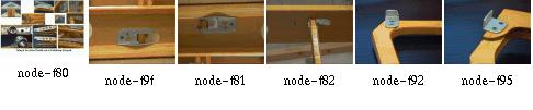
This is the nicest folding Kayak I have seen so far (Hendrik), the joinery is a dream:
Stern Joinery
Frame and Gunwale Joinery

Gunwales
Design Sketch
Here is Gerald's original page with more info on his design.
And here are all available pages:
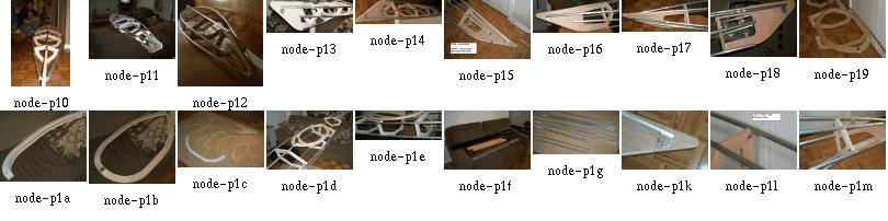
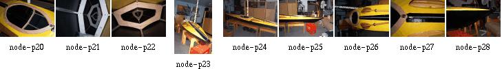
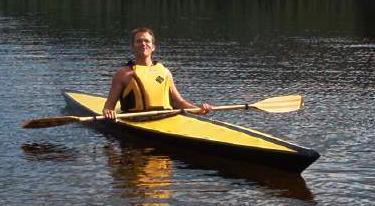
 Patrick built his kayak in his living room. He plotted the sections
to scale 1:1 and glued them on 4x4ft baltic birch sheet. That's why
you see white paper on section backs.
Patrick built his kayak in his living room. He plotted the sections
to scale 1:1 and glued them on 4x4ft baltic birch sheet. That's why
you see white paper on section backs.
Patrick has used a small brass hinge to connect the cockpit halves.
The skin is black and yellow PVC coated polyester mesh 16 OZ, 0.5 mm thick bought
in a truck tarpaulin maker shop. For 100$ CAN he got all needed
fabrics plus a quart of HH-66 vinyl glue.
When Pat has created the DXF the view scale was "1"
so normally when you will print on
a plotter the scale will be ok. But not all plotters
can print that size of paper so to use it
you have to divide in four equal parts and separate
in four different files. Don't forget that little detail.
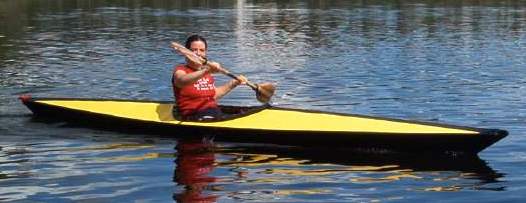
On vacation in August 2002 Pat went with his friend in their
chalet on the shore of the small lake Dubuc in deep wood on
Mont-Valin a chain of mountain in the north of
Sagnenay river. He is from Jonquiere, a small city of sagnenay
region and brought the kayak with him. First real trial
while fishing rainbow trout and being by mosquito's!
Pat's hull design is made of four parts. Separation approx 1-1/2
feet after stem and stern and one separation in the middle.
He removed all the wrinkles with an iron set to medium
and a cotton shop towel to avoid sticking. This works as well as with a heat gun.
Based upon my own experience, wooden sections are preferable
over aluminum sections because they don't deteriorate
so fast (bending, buckling, denting). HDPE is even more
versatile, but considerably heavier than wood. All in all,
a really good design, especially for the first one you do.
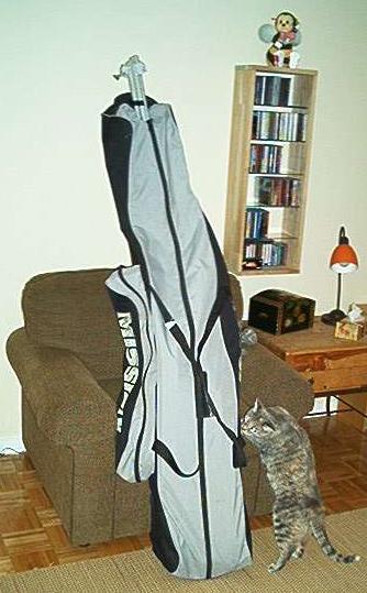
At the left is a pic of a new used hockey bag with all the kayak in it.
Like you see on the pic there is a little measurement error but it is the
perfect bag.
Push and Secure
Pull and Secure
Rotate and Lock
This and That
I keep receiving questions about making PVC skins and thus have re-edited my comments about it into a single file that is a little easier to read. Now you see a mix of four years old comments with very recent ones.
Questions and comments by others are printed in blue.
The images are clickable and lead to the full-size (original) pages.
[ Skin Material ]
[ Welding ]
[ Skinning Sequence ]
[ About Tape on a Final Skin ]
[ About Temporary Skins ]
[ Lacing Skins ]
[ George Dyson's Hypalon Skins ]
[ Thomas Yost's Hypalon Skins ]
[ Epilogue ]
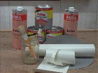
In short, the idea about glueing PVC is to use lots of thinner (Acetone). I had to test the mixture several days and came out with that it is right when the thinned glue begins to run off the brush by itself. Then apply it minimal two times to both surfaces. After letting the glue get nearly dry, combine the two PVC parts and press them well for some minutes.
 For the first prototype I sewed two strips of PVC onto a zipper
and glued these zipper strips at the middle of the deck piece. This feature
was as strange as convenient;
it eased assembly and loading of the boat.
For the first prototype I sewed two strips of PVC onto a zipper
and glued these zipper strips at the middle of the deck piece. This feature
was as strange as convenient;
it eased assembly and loading of the boat.
With some grief I dropped this idea and the actual design now has hatches
instead of the zipper. These hatches serve the same purpose except that
it is a lot more difficult to assemble the boat. Also I do not have these
sponsons any more that had to stretch the skin.
Anyway, the www site of STAMOID is http://www.stamoid.com/stamoid or http://www.forbo.com and they have some property sheets about that specific skin material.
The skin comes in doublesided or singlesided PVC covering on a polyester fabric. singlesided weighs 280grams/square meter, doublesided is 430g/m2, tensile strength is better than 1200N over 5cm width.
The singlesided stuff is covered with a dirt protecting finish, which makes glueing and welding impossible and thus has to be removed in the contact area.
Paul Raymond wrote: I stopped at a canvas store today, and he sold me 17 feet of double sided Stamoid for $100, which I think is a good price. Since this is for an aluminum folder, and Hendrik Maroske used it with success, hopefully I will too. I'll find another use for the pack cloth.
Stamoid is what I have used, it comes in both protected and unprotected versions. I suggest to get the thinnest material available, that is, I got the 0.6mm stuff and found it too heavy when glued together, so I talked my supplier into buying 0.5mm stuff for me. There even seems to be 0.4mm material out there, and a way to get material with defects (holes) in it (lots cheaper). This material is so thin compared to my Klepper, how does it hold up on your boats compared to commercial boats? Do you still prefer Stamoid to any other material available?
My most recent Baidarka still is the one from the 1999 Toronto trip. The Baidarka skin was finished late summer 1998 and I must confess I did not use the boat very much since Toronto. I have moved the workshop since, and with it the boat, and since that move the lake is a little more difficult to get to (without car).
Anyway, the pics on this website with several closeups of that particular skin have been made during Christmas holidays January 2002, so you have a guess at how good the skin actually is. It still looks "new enough", is tough as ever and still waterproof. No seams broke.
The skin is nearly four years old, the "unprotected" Stamoid, and ready to go on any trip. I'm satisfied with it. Always cleaned stains before they could wear in (with water only), because without the protection I am afraid to use chemicals to clean the skin.
I see that Tom Yost used polyester material, and then coated with hypalon, which worked well for him, but I wanted to avoid having to use toxic coatings, and the pvc material seemed quicker to skin.
To each one his way looks as the best afterwards. But I would still do it again. It took some time to learn to use a good balance of techniques, stitching, glueing, welding. Basically, my experience with Stamoid and Pattex and Acetone is that if the glue doesn't hold within the first five minutes, it never will. Throw away the pieces that you can and restart. If it holds, it always will. And by "holds" I mean you rip the pieces apart and not the glue fails, but the Stamoid goes apart.
Practice good bonds before doing the skin.
And even more basically the only advice I can give is to really do a few practice runs on the stem and stern pieces with the intention to keep them as samples. This will pay out in the end. Use double sided tape for the first practice run to have a good chance to rearrange things and if you don't want to wait for the glue to settle.
And, talking about abrasion, I cut Stamoid in strips and these were formed with a heat gun to match the curving of the hull before glueing them on over the stringers and where the skin pieces meet.
Generally the heat gun helps a lot to smooth out the results. Afterwards, the warm material is perfectly dry for glueing. It seems that there is some amount of (water or other) thinner in the skin that works against a good bond. Seems to be the stuff that makes the PVC soft.
There's different stuff available for glueing non-rubber zodiacs. 2-Komponent and stays flexible, although quite expensive
Welding is used only in professional applications for truck and tent awnings. I got caught by approximately 3mm material shink per meter as I welded the 5 seams in my hull. Makes funny waves in each section. Took me some time with my heatgun to shrink the whole skin, to take the worst away. :-(
Amateur tools for welding soft PVC without glue, just fabric on fabric, are air guns or the like. Their actual use and temperature operation range seem to fit. Use a rubber wheel on a stick to press the layers together. When it becomes black it's too hot... The professional heatgun that I used only melted the pvc surface without allowing for sticking. Something obviously wrong in my procedure. Welding was Gerald's idea, and for him it worked. My (Hendriks) heat gun did cause some degree of sticking, but not enough to really call this welding. It depends very much on the quality of the skin. If there is anything like "abrasive protection" or "dirt protection" put on it, forget about welding. What becomes black ?? PVC does not seem to change any colour. Is it the glue?? I guess that Gerald was joking. My white PVC just got darker and started fuming. Then it's time to rapidly stop heating. Final question not yet answered: do you stitch only for keeping the pieces together ? In other words, does the skin in its final version rely only on glue lines or is it glued and sewn. I could not really get this out of your description in previous postings.
In my case, stitching was used until the glue bonded permanently. After that time (some 15 minutes), the seams were removed where possible.
All your help is precious: I have just bought wallpaper and a range of water based markers to start the skinning job.
I got the wallpaper trick from Gerald, and it's worth it. You'll easily see how it will be with the PVC, since PVC doesn't have much more stretch than the wallpaper.
One thing about heat gunning:
I never was able to really shrink the skin. It's more like
rearranging it to stress, so that folds and waves remove
themselves. If you would really _stretch_ it with heat,
it will cool off and then be over-stressed and floppy.
So, I used the heat gun only for aesthetic corrections,
not for shrinkage.
Paul Raymond wrote:
Has anyone else had any luck using pack cloth, which comes coated one
side and dyed, and adding additional polyurethane?
Michael Daly wrote:
I have never tried, but wouldn't bother. Coated pack cloth, in addition
to having a urethane coating on one side, has a durable water repellent
coating on the fabric as well. The purpose of the latter is to prevent water
absorbsion into the thread and so enhance its waterproof properties.
I'm willing to bet this coating is what prevents a good bond with the
subsequent polyurethane coatings you apply. You need an uncoated fabric to begin
with, or at least one that has only a "coating-friendly" treatment applied.
Preventing any good bond, exactly. I had oversensitized my right thumb from rubbing the material with Acetone to remove the protection from the glue areas. Definitely NOT the way to go. Although the coating really is good, waterproof and repelling dirt.
Stefano Moretti wrote:
I need much help from more experienced skinners. This will be my first
attempt. I've finished the frame od the foldable with much satisfaction. It is
not wobbly as when I first started.
Congratulations! Now proceed to game level 2 :-)
1) Make hull and sides from one single piece, cutting "V" shaped slots in bow and stern. Seen this picture in FOLBOT virtual company tour.
No way. I also tried this. It is better to do it right, from the start on. Buy a roll of wallpaper and make cutting patterns. Cut the patterns in stripes following the chines, guns and keel.
2) Overlap hull and deck skin over the gunwale chine by more than one inch
Again, its better to go right through it: begin with a large overlap for sewing and then cut it small before glueing. The skin is not easily folded with such thick glue strips.
From my experience, I consider everything too thick that is overlapping more than 3/4 inch or has more than two parts overlapping at the same area
3) cutting deck from mid cockpit to bow, and from mid cockipt to stern, so to reduce the wrinkles and dragging all error towards the cockpit area where the big hole would accomodate much wrinkling. Done this with 3 mm plywood in clc kayaks, should work.
The less glue strips (rsp. easier folding), the better. If you go without deck ridge, there's no need to go with the deck seam. Always proceed to the ends rather than towards the cockpit. Otherwise, you end up having a slack skin at the cockpit.
4) for all unexpected problems and some extra stiffness (still very much debated I know) I would add two small section sponsons just below gunwale.
In my case, both designs worked well. Especially with cold, wet skin, sponsons give you the chance to re-stretch it.
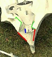
How do you cut and glue around the Aleut stern.
Making these end pieces helps a lot in acquiring the skills to work with PVC. Throw away a piece if you are not satisfied. The next one will come together a lot quicker.
Having made a pair of useful end pieces, the large skin panels are glued over the end pieces, and when all the skin is done I add a nice looking finishing layer over the end pieces, smooting out the curvature and hiding all the seams, glued patches and the rugged connection between skin and end piece.
After having made the skin, I rip out the innermost PVC layer of the end pieces, thereby ensuring that the stem and stern will always slide into them without too much trouble. So, the very first PVC layer for these pieces is attached only very temporarily, with double sided tape or masking tape.
Do your PVC skins have a seperate panel for each Keel to chine, Chine to gunwale, and gunwale to deckridge, or are you able to cover greater areas at once?
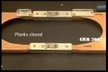
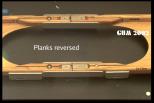
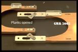
Greater areas simplify nothing. They make things more complicated, and if something goes wrong, you'll have to throw away more skin. My boats have fairly high gunwales, more like 'planks'. The sequence is like this ( I began inside-out, here's a sketch, but that is not absolutely necessary):
What weight PVC would you recommend ?
The thinnest/lightest you can get. I have used .6mm thick stuff and next time will definitely use .4mm instead. Because every seam doubles the thickness, and together with the glue it really gets stiff. If you expect trouble somewhere, use the thinnest stuff you can get and apply strips wherever needed. The procedure for the stem/stern I described yields very stiff results.
From now on I assume that you have made a set of good end pieces and are ready to skin. PLEASE, use wallpaper for making cutting templates. Cut strips aligning to chines, guns and keel. (in my case, 6 strips + 1 deck strip). By any means make strips the whole length of the boat. Leave out cockpit rim.
On the inverted hull, sew together the two strips that meet at the keel and go up to the chine stringer.
Sew strips loosely together using 1 inch spacing between seam stitches. Sew only where PVC is cut away anyway. This routine worked best for my Greenland Baidarka with only one chine stringer and the gunwales having an upper and a lower stringer.
I used a twohole punch to make a row of holes at a long side of a large piece of PVC and temporarily sewed it directly onto the frame prior to glueing it to other pieces. This way I could reduce the count of folds in the skin.
Sew the two strips that go from guns to chine to the ones you just sewed together, leaving off the stripe between lower gunwale and chine and thus using large seams over the hole (stitches 5-7cm apart).
Loosely attach the previous mentioned strips to the guns (stapling them on wood frames, using tape on aluminum) and rotate the hull
Sew on the deck strips with a rough seam, stiches some 3cm apart
Use heat gun to remove wrinkles everywhere. Rotate hull.
Use heat gun to stick (weld) the remaining two strips to their place between the lower guns and chine stringer.
Remove the large seams under the two newly attached strips. Use heat gun to partially lift off those strips and reattach them without wrinkles.
Lift one yard of each strip, clean contact area thoroughly, apply "hendrix mixture" and glue them together. Make sure glue line is only 1.5 - 2cm wide. Glueing procedure described later. Work towards the ends of the hull, cleaning and glueing.
Let the glue dry. Cut excess skin at the newly made joints.
Use heat gun to remove wrinkles. Do not generate excessive heat at the glue strips!
Redo the keel seam (the butt type, not overlapping!). Now space the stitches 1cm apart. Cut excess skin. Now the borders of the two skin strips just touch each other.
Use heat gun to remove wrinkles at keel area. Cut keel strip (3cm wide) and lay it over the keel. Use heat gun to smooth it over the keel's curvature.
Remove keel strip, clean keel line, 1.5cm in each side (=3cm wide total).
Remove keel seam for two foot length, glue the keel strip where the seam was, to make it watertight.
Redo gunwale seam. Proceed as with keel.
Glue small horizontal skin strips over the bow and stern to generate the Baidarka's extremities. For Greenland Kayaks, much less work since larger patches usable.
Cut and seal the cockpit area.
Don't forget to make sure there is no "protective impregnation" of some sort over the PVC. Otherwise, you get lots of additional work to clean the glueing areas.
Be meticulous at the cleaning operations.
Always make test specimens and rip them apart to see whether the glue mixture and/or cleaning operation was successful.
Well, "hendrix mixture" goes like this:
- thin the glue until it quickly runs off the brush by itself.
- thoroughly mix
- apply three times, let dry after each application
- contact the parts
My glue is the German "Pattex Transparent", thinned with Acetone. You might want to ask my brother Gerald, who is a chemistry professional, what the american equivalent is.
I put a rub strip over every seam and have had good results.
In my first attempts, I also have put rub strips inside the skin; this is not so good, since skin folds less easy, is more heavy and tends to develop folds. Also I simply cannot glue well on the frame from the inside.
On my first foldable Baidarka, the double sided tape that had to closepart of the deck seam and seal it watertight, became an ugly black smeary, slimy thread after a two-week saltwater session. I'll never do this again...
Now, it seems that most of us just try with the expensive skin (me included), ignoring the possibilities of tape (although I tape virtually everything) and clear plastic. I just always had tried to avoid the additional work involved.
But that can be real fun; here is an account of what can be achieved, if you really want.
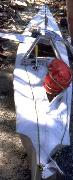
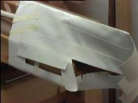
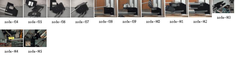
Tom writes:
This temporary folding skin is made of PVC to test the
viability of the material as a one piece hull.
In this test, I've pulled the skin fairly tight using
squidding line but am careful not to
over stretch. There are still a few wrinkles in the
skin, but to this point no heat has
been applied. The "Real" skin will be made of higher
quality, thinner, Stamoid PVC.
This is a good picture. I have seen this quite often with my own first PVC skins.
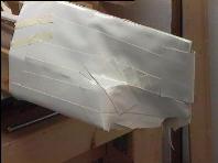
My own experience at working with very large PVC skin panels is that bulges develop at the few remaining seams which show that the skin doesn't fit closely. These bulges were quite sharp since in the other places the skin would fit very smooth. Afterwards it was impossible to remove these bulges.
If you look closely, you will see the vertical folds in between the gunwales and stringers. This is exactly the problem zone, they tend to concentrate right before and after the cockpit. On the other hand, the keel area looks good... how about a single piece for both keel panels? Now, the keel needs a rub strip anyway, so there is also no real advantage in doing it in one piece. Doing it in two pieces yields much smoother stem and stern parts. You will find that narrow PVC panels are much easier to work into a pre defined shape.
My own conclusion is that a one-piece skin is perfect for testing the frame before doing the final skin. This one took less than three hours to make. Very motivating.
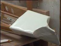
Tom writes:
The Stamoid has unidirectional fibers which would only conform
in one direction, so it wouldn't take the shape of the hull
without getting all wrinkled at the stringers. In addition, and
the thing that bothered me the most, was the fact that the Stamoid was easy to tear when I
pulled on the stitching that I used to stretch the skin. This
happened in only one direction , parallel to the fibers.
I've never had a skin material
tear before, so it really caused me concern.
I still feel that a one piece PVC hull is workable, as it has been
done by others. The problem I had was trying to do it with Stamoid.
The black PVC had
multidirectional cloth , the same that I use on my sewn skins, so it had
the ability to conform to the stringers. I didn't have enough of it for
the entire boat so I
purchased Stamoid thinking it was made the same way. It wasn't.
About the Stamoid tearing easily when sewn; that is a good point. If I recall correctly, the thicker 0.6mm variant would not tear as easy as the 0.4mm one. Anyway, I had no other comparison and was satisfied with the 0.6mm stuff. Although I have never seen a skin tear on my boats, even on tar or stone beaches. And back then I simply took it as normal, but shame on me, I have used only a small amount of really thin Stamoid, mostly using the 0.6mm material. I stand corrected in having said the thinner material is better. Maybe the thicker material has a stronger cross weave respectively more cross weave?
Here is what I found today, 28OCT2002 when measuring the tearing resistance with a thin line that I would use for sewing the skin (25kg test Dacron). I punched the "sewing" holes an inch from the border and an inch apart:
Direction crosswise to roll length (in roll axis):
20kg,18kg22kg (average=20kg)
Direction following roll length, that is, the fibers,
if fabric were of unidirectional fibers:
12kg,14kg,20kg (average=15kg)
To me the difference doesn't look so alarming, but yes the Stamoid actually is not at all multi/bi directional.
During my boat building runs I noted a rather large variation in quality even in a single roll. Also, the material sample I just have tested is 0.55mm thick instead of the supposed 0.6mm. The resistance to tearing with a strong line also varied a lot and was kept at bay in using a small distance between stitches. In the end I glued everything anyway. Also I used to use a thinner, weaker 10kg line that would rupture before the skin would tear and would not interfere with glueing.
I never could achieve anything with "lots" of heat shrinking on Stamoid. Only with narrow strips that were formed with the heat gun. Heat only re-aligned the weave within the PVC very lightly.
I also have heard of several people trying a one-piece skin, but my own results were frustrating (see above). See here for Patrick Poirier's results.
I know several people who have used hypalon on folding skins and I haven't heard complaints. Of course, commercial folding kayaks and most inflatable boats also use hypalon coatings, but those are impregnated under pressure and thus bonded more completely. But it is a good sign that the river rafting industry has stuck with hypalon for at least 20 years.
I should have all kinds of free time since I finished my new book, but I still haven't found time to revive the BHS. Fortunately, the skin boat revival has a life of its own, and is doing fine.
There's an excerpt of my new book, with discussion, at:
best wishes,
George B. Dyson
 Click here for a
view of a Thomas Yost's design for a folding Hypalon skin.
Click here for a
view of a very easy method of lacing the skin to the frame.
Click here for a
view of a Thomas Yost's design for a folding Hypalon skin.
Click here for a
view of a very easy method of lacing the skin to the frame.
"what's that"
I answered "my boat".
"a boat?"
"yes. It's a Baidarka." Having said that I thought he'll ask something about what a Baidarka is. Especially some question about that bow. Instead came
"why'd you wrap your boat in plastic?"
Click here for
Thomas Yost's design with a folding
hypalon skin.
Click here for a
view of a very easy method of lacing the skin to the frame.
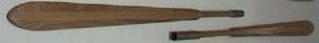
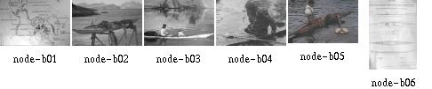
Gail Ferris' paddle drawings are barely visible in thumbnails, but worth looking at in fullsize!
Paddle Drawings by Gail Ferris:
Curved Bone Up
Ilulissat 1 bone edge
Ilulissat 2 bone edges
Kitdit Vestejland
Lars Jensen
Nathanial Jensen
Neils Moller
Odense Upv 97
Weathered Upv 97
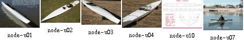
What you're looking at is just an overview with a few interesting images. Here is more info on all our folding Baidarka designs:
[Design]
[Construction]
[Parts]
[Joints]
[3-D]
[Complete Framework]
[Skin The Frame]
[Stem]
[Stern]
[Rudder]
[Gunwales]
[Frames]
[Stringers]
[Cockpit]
[Materials]
[Pump]
[Sail]
[Paddle]
[This And That]
Well, the basic folding boat design procedure goes like this:
That was actually step one.
That was actually step two.
That was actually step three.
That was actually step four.
Still reading?
We actually have managed to collect a few useful design and construction tips,
and the purpose of the design page is to divert you into the appropriate sections, depending
upon your preference.
Since this is a 'crosswise' entry,
you will have to use the button to get back to
the design page.
Design bits and pieces:
SPY-10 Sailrig by Thomas Yost
Dyson Style Two-Seater Folding Baidarka by Thomas Yost: Seat and Frame
Zippers: Easy Loading
Deck Ties
Skin Quicklace
BIF-16 by Thomas Yost: Perfect Bow
Sliding a Curved Bifid Bow Into The Skin
Oval Aluminum Tubing
Thomas Yost: Bending Tubes
Bending Aircraft Tubes at Mark Smith's Shop
QUESTION: Pin Joint for Stringers
Skin Cutter
The PVC Glue
Kayak Camping: My Sail is My Home (Ready for the Night)
Epoxi
Rudder Pedals After Use
Simple Carrying Toggle
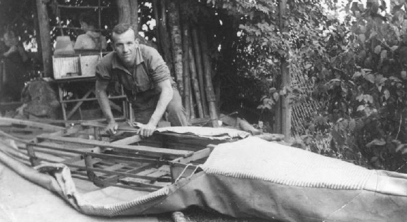
This is my grandpa Martin Seeger with his folding kayak, assembling his own design. He is not exactly a contributor to this page but my thanks go to him anyway. He'd have a lot of fun with this page...
This pic is dated about 1928, for all the folks who think they invented the folding kayak :-)
well, that's it :))) Tonight for the first time I disassembled the Folding Greenland Baidarka from within its skin and was able to get all parts out if it :)
Well, nearly all... I had overseen a tack which permanently fixed the skin to the keel right where the rudder is and where nobody can reach the tack to pull it out! The good part of the story is that I have sewed only partial deck covers. I will not glue the final deck cover onto the skin before the cockpit sock is ready and the equipment bags have been fitted to the hull form and attached to the hatch closures. So, for quite a while, the Baidarka will stay without the final deck cover. This is no problem since I already have cut the piece and can glue it on within an hour or so.
With my aluminum Baidarka, the first disassembly was more of a disaster. I had skinned it over the xmas holidays while my family was out. The Baidarka occupied our whole living room. Two hours before my family returned, I was ready to disassemble. It did not work. A stringer was fixed by the skin and could not be removed without sawing through the aluminum tube... I picked up my wife and kids, and they went in and I brought their luggage up and carried the Baidarka sack down, living room looking a bit untidy. That was a close call...
Anyway, here is how my brother Gerald and I have once assembled our kayaks in the field, entertaining the whole small village for the best part of a whole sunny day:
This sailrig is designed for use with FAP-16. It can be adapted to other folding kayaks with minor modifications. The amas are constructed using aluminum tubing, HDPE Cross sections, and a nylon/neoprene skin.
This ama design is based on, but not a copy of, the Chesapeake Light Craft Eight Footers that appear in Woodenboats #131, July/August, 1996. The CLC amas are made of plywood and feature a "V" shape cross section. The SPY-10 folding ama utilizes aluminum tubing with a nylon/neoprene skin. The cross sections are "Hard-Chine". The amas are 10 feet long to approximate other designs currently in use.
With 3 cross section and 3/4"X.035 tubing, the amas weigh 7lbs. each. Estimated weight with Nylon/Neoprene skin is approx. 10lbs. each. The 120lb. displacement figure is at point of submersion. The twin 10 foot akas are made of 1.5"X.049 tubing and break down into three sections. The center section is 4 feet, and the outer sections are 3 feet each. There are two 27" inserts per aka, which are made of 1-3/8"X.058 tubing. The akas are spaced six feet apart as Tom felt that was a minimum distance for paddle clearance.
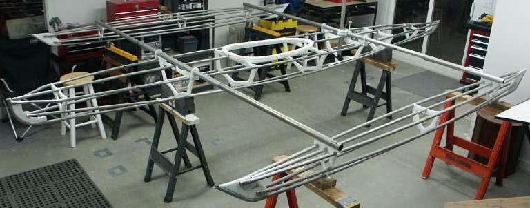
Tom's workshop is pushed nearly to it's limit when the sailrig is assembled.
These are boats (and nuts). They fly and ride trains and buses at no extra fee (the boats, not the nuts).
Carrying the kayaks in airplanes, trains, buses and taxis was no problem; all american transportation had facilities to handle bags of that size. Even with the Victoria Clipper, from Seattle to Victoria, this was no problem, although they had all their staff carrying our luggage on board. It might become one, when everyone tries to carry luggage of that size...
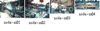
What has a motorcycle to do with kayaking? Easy: the taxi driver very kindly drove us around with our large heap of luggage. He is a Harley Davidson expert and might have all the parts you need for your pre-war bike. We had some time left when we were to go to the ferry, and instead of just dropping us off, Tony showed us his workshop.
The Lightest Breeze
The Lightest Breeze Enters My Mind,
And All Before Is Left Behind.
For It Is Not Fate That Brings Me Here,
But Rather A Need, Perhaps A Fear.
The Winds Of Time Have Happened By,
And Left Me With This Clear Blue Sky.
The Ocean Swells Do Comfort Me,
The Waters Glow, My Light To See.
For All That Is Will Always Be
Deep Inside A Part Of Me,
Until My Life Upon This Land
Assumes It's Place Amongst The Sand...
T.Yost
George Dyson's ''Mount Fairweather'' Baidarka was launched in June 1975 at Vancouver City and some days later made its way up to northeast Vancouver Island. The summer solstice of 1995, nearly exactly 20 years later, my brother Gerald and I enjoyed a trip to the Discovery Islands. This trip also was a test of my brother's newly built folding Greenland Eskimo Kayak.
We crossed paths with George Dyson's and similar expeditions. In part, that trip was a sort of a ''dream-come-true''; inspired by our reading and re-reading of George's and Kenneth Brower's books.
Compare the characteristics of our kayaks and let me point out these inspiring journeys, so much more than what we have achieved:
Perfect paddling weather. The way I got there was this: on a Friday noon I was working in England on a piece of software. Already a taxi was waiting to take me to the airport. At the same time, one of my bosses showed up with a commanding voice and a ticket to Toronto. So I repaired that code, got my plane home to Germany that Friday, packed the Baidarka on Saturday and catched the plane to Toronto on Sunday, showing up on the check-in with a previously undeclared bag of 2m times 50cm times 30cm weighing 90 pounds. It was an eventful check-in, but eventually the bag got on board for about 200 US dollars.
Nearly two weeks later, still in Toronto,
I managed to get a long weekend off, but I would only know that
I am off when I already sat in the car, driving north. Whew.
Dear Friend, now this is the end of our story. It started out as a dream and now has become reality for us. That other reality that we have to live in is already waiting for us to return to.
Wondering why it is this way
Spending Time for Naught.
Wasting The Best Hours of the day
Knowing my Soul is Bought.
For Working Here Is Life Passed By.
Freedom Traded For A Clock.
I'd Rather Be Sitting Under a Tree
Staring At a Rock.
Contributed by Thomas Yost.
I hope these pages contain something useful for you; if they get known among some home builders, that's fine. But you can imagine that none of the authors will like to see his pictures spread out and sold without knowledge and permission; so please respect their property. My thanks go to all contributors. Most of the addresses listed below are unfortunately out of service now.
George Dyson, the classic in this field (thank you for the superb fotos)
 gaileferris@hotmail.com
Thomas Yost Littleton, Colorado 80122 (Your pics are the salt in this soup :)
Gerald Maroske (without your ideas this wouldn't have happened)
I also owe more than a "Thank You" to these editors
of books and articles:
John Brand (Little Kayak Books)
H.C. Petersen (Skinboats of Greenland)
John Heath (Articles in SeaKayaker)
Nikos Drakos, head of the "latex2html" team for
their TeX to HTML converter
David Walker for the cool 100percent sticker (greetings
to all Linux users :)
sure the developer of the origami folding text editor without which I'd have a lot of trouble writing these files because my setup is a lot faster than cashware :-)
and last but not least Charles Hall who went through the work of making the robroy server and Baidarka CDROM where this slide show and a lot more can be found.
 , thanx Linus!
Those things were built to make a living; not just for sports.
For a description of baidarka designs, click here.
Image size: 1359x527 pixels.
Curved shaft whitewashed old paddle with bone tips found in the loft over the church
Measured and drawn by Gail Ferris. Dec 4th, 1997.
Gail E. Ferris
Image size: 1681x677 pixels.
Paddle with single bone edge at Knud Rasmussen Museum, Ilulissat
measured and drawn by Gail Ferris 6/23/95
Gail E. Ferris
October 18, 1998
Image size: 1811x751 pixels.
Paddle with two piece bone edge at the Knud Rasmussen Museum, Ilulissad
displayed on the third floor. Measred and drawn by Gail Ferris 6/23/95.
Image size: 1997x661 pixels.
Kitdit or Vester Ejland paddle at the Aasiaat Museum
Measured and drawn by Gail Ferris 06/22/95
Image size: 1673x617 pixels.
Lars Jensen, son of Nikolaj Jensen, Kullorsuaq Greenland kayak paddle specifically
designed without a rib down the center
Measured and drawn by Gail Ferris 9/95
Image size: 1436x636 pixels.
Nathaniel Jensen paddle designed with a ridge down the center to split the
vortices by Nikolaj Jensen, Kullorsuaq, Greenland
The shape of the blade cross section at 2cm is a long rectangle with rounded edges.
At 20cm the cross section is an ellipse without any rib down the center.
At 25cm the rib on the face of the paddle blade starts to form and at 40cm
the rib becomes highly defined.
The loom begins at 76-77cm where there is a step down.
length overall: 217cm
length of loom: 61cm, rectangular
blade length: 77cm
Measured and drawn by Gail Ferris 9/95.
Gail E. Ferris
Image size: 2317x777 pixels.
New paddle made by Neils Møller at the Upernavik Museum
A thin blade with a shallow taper
This new paddle was very smooth of light yellow fine grained wood, without bone ornamentation and an elliptical cross section.
Similar paddle on Rosa Thorliefssen's father's kayak in Innarsuit which also was very likely the standard paddle in the 1930's (very light and especially long).
Length: 226cm
measured and drawn by Gail Ferris 6/29/95.
Gail E. Ferris
Image size: 1849x705 pixels.
Kayak paddle collected in 1890's given to Upernavik Museum from Odense Byter Museums appears to be
very similar to a paddle Gail Ferris measured June 1995 from Kiidlit/Vestejland, an Island
on the western edge of Disko Bay.
This paddle has a very distinct ridge down the middle of the blade which the paddle from Kiidlit did not have.
This is a very thick paddle.
Overall length: 200cm
Bone edge is 1cm wideby 39cm long by 0.75cm thick.
Bone tip is 8cm long
ransition from paddle blade to the shaft starts at 75cm from the tip.
You asked me why the diamond shape in Nathanial Jensens paddle affects the wake vortex configuration by splitting them. Well Nikolaj Jensen and I both agreed that the annoying thing about a flat faced paddle is that the paddle chatters or wavers up and down in the water during heavy acceleration. And so to eliminate this is to make the paddle blade face diamond shaped.
I think the best way to discribe the effect of a diamond shaped paddle blade face is that it causes wake separation sufficient during start-up acceleration to eliminate the combining of the wake from the power face and back face from generating perceptible wake drag. The wake generated on the power face is divided into two simultaneous wakes one on the top and one on the bottom of the face instead of one alternately coming off the top and then again off the bottom.
Also I think if you look closely at the unusual shape of both the Odense and most particularly the Kitdit paddle you will see that there is a highly exaggerated roundness at the 40 and 60 cm. sections where the wood junctions with the bone edge of the paddle forming a concave area at the juncture of the bone with the wood. I noticed this very extreme juncture area and wondered why it was so rounded up rather than delicately flattened to a nice gentle integrated line with the bone and wood melling together with no concavity rather a gentle sloping shape.
Gail E. Ferris
October 18, 1998
Image size: 1845x689 pixels.
Weathered thin old paddle found in the loft of the old church. No ridge down the
center, elliptical ends, softly rounded without ridge down the center of the
blade. Such a thin narrow blade is just the opposite of the Kiitdit blade
which I suspect must flex when applied from a standing start. Shaft is
a rounded square.
Overall length: 226cm
Transition to rounded square shaft starts at 85cm
Transition to paddle shaft on the edge of paddle starts at 65cm.
Measured and drawn by Gail Ferris. Dec 4th, 1997.
Gail E. Ferris
I live in Upernavik Greenland where we have a continual parade of
Icebergs. Every time I go paddling I think about icebergs, what
they are doing and what they might do. Icebergs are always
challenging because no two icebergs are alike.
Even though an iceberg may not appear to be quite as fantastic as
the monstrous, tunneled icebergs I have seen in Blomster Bay in
King Oscar's Fiord of Northeast Greenland, still for those of us
who venture on the water in our fragile kayaks, any iceberg is
to be respected. Icebergs can be extremely deceiving, especially
when a big iceberg has done very little for a long time. Then it's
easy to become used to it as just another mountain of ice just
sitting quietly on the water and it don't seem as though it can be
such a threat.
But icebergs are full of surprises and one big surprise can be those
hidden dimensions beneath the surface. The last time I was paddling
decided to make a crossing that would be few miles and to start
from an easily identifiable point. So I choose what simply looked
like two small grounded out bergs. The only thing that seemed just
a little bit odd about these two icebergs is that they were the
only two icebergs side by side and there were no other icebergs near.
It just seemed unlikely but I thought that perhaps the current was
just right at the moment they landed in that bay and then by unlikely
chance happened to have grounded out there together. It didn't really
seem all that likely but I just assumed that anything can be possible
with icebergs.
While I was making the crossing and found myself precariously out
in the middle feeling very vulnerable because refuge was a mile or so
either way, I heard a thunderous crash. And judging from the tone of
the thunder, this was definitely from a large iceberg that was doing
more than just dropping off a few pieces. The sound seemed as though
it could have come down around the bend in another passage. However
the sound could have been an echo from an iceberg that is next to one
of the nearby the cliff faces.
I stopped paddling and carefully scanned all the bergs in sight just
to be sure that there was no steep wave bearing down on me from out of
nowhere. Surfing is nice and I enjoy experimenting with the dynamics
of waves, but as a solitary cold water paddler, I don't like
surprises like being overtaken by a wall of water. I continued the
crossing without any surprises and I just had to make some minor
corrections for current set. I enjoyed looking in detail at the rocks
studying the formations and enjoying the sculptural abstract shapes
of eroded granite.
This is one of those fine moments, which makes kayak paddling such a
pleasure. When you are in a kayak you are experiencing active water
directly and when you are looking at eroded rock you are seeing
what water does to objects that don't move of themselves but
are moved by water. What's unique about an icberg is that it interacts
with the water as a stationary object being eroded and as a floating
object.
But this is only a small part of the spectrum. An iceberg is exposed
to a constant interplay between different temperature stresses. The
entire structure of an iceberg is a product of it's creation with
unequal structural stresses throughout. So you have this constant
shift in dominance of internal structural stresses pieces fall off,
the whole thing splits, the water currents are constantly eroding the
foot, it can ground out and suddenly the center of gravity abruptly
changes and the whole iceberg rolls over. Now you have an entirely
different shape with a new set of internal stresses vying for dominance.
So when it comes to icebergs there is always something happening and
that is what makes icebergs so endlessly fascinating. After I had
enjoyed myself feasting my eyes savoring this unexpected treasure
of abstract forms it was time to head back across the passage. Now
the confusion set in when I turned and scanned the horizon for my twin
iceberg starting point because everything even the twin icebergs
just seemed to blend together. I was looking for distinctive landmarks
on Long Island, which are in the 50-meter range gently rising to a
maximum of 200 meters.
Coming from the opposite side I had been using landmarks such as the
680 meter Umiak Mountain, a valley and long expanse of columnar
basaltic cliffs which are nearly impossible to miss unless it's
hopelessly foggy. On the return the landmarks were so lacking
definition and even the islands melded together making them look
like one massive island. "Wow," I thought to myself; "I didn't
expect this." If I had I would have turned around a few times on the
way over just to familiarize myself what the land looks like as I get
farther and farther away from it. Oops! I toldmyself "I am usually
more careful than this. You are getting lazy and overly confident."
I calmed myself and started across remembering that I had come on a
diagonal.
All went fine and the two icebergs came into view so I headed for them.
Then just as I was passing them, suddenly there was a huge crash on the
shoreward side where luckily I wasn't. A chunk fell off followed by
more small chunks of ice and I thanked my lucky stars that I hadn't
decided to come in for a landing on that shore because the waves would
have just grabbed my kayak. Such a large amount of ice fell off that the
center of gravity changed. Next the two icebergs revealed themselves to
actually be just one large berg joined beneath the surface by a bridge.
The end nearest me reared out of the water then rolled part way back
under the surface until the berg restabilized on it's new center of
gravity. Now I realized that this berg was easily more than three
times the original size of what I thought it was as two small bergs.
I was glad that I hadn't passed by on the restricted shoreward side or
any closer than I was. I usually carefully decide on the danger limit
of a berg by its size.
This time I had been tricked and I rethought about my original
assumption. One thing that is definite; never assume anything about
icebergs.
Gail E. Ferris
October 18, 1998
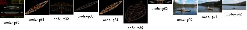
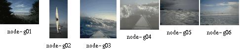
Now, that you've come through the thing show here, let us return to where it all started: the bias towards aircraft, that seems to connect a few baidarka builders. In my introduction I already gave you a few hints about hidden aircraft parts in this show.
The question: what do you think is the total number of different homebuilt aircraft, which are shown totally or of which parts are visible within this show?
The answer is on the bottom of this screen.

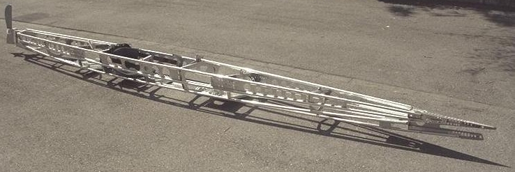
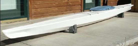
The frame features only two separation points per gunwale, which means that it can be competely disassembled and then the gunwales split into three pieces each. This results in a very strong frame; the drawback is an increased weight compared to the original. The advantage is an unprecedented mobility for a baidarka.
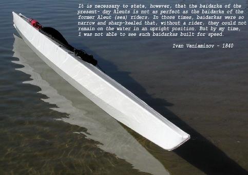
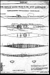
The empty ''Nevermore'' baidarka is 5.16m long (with rudder 5.30m), has a beam of 55cm and weighs 26.5kg (without sail). The whole expedition equipment are two bags of 32kg and 20kg. About $200 were spent for the skin; $70 for aluminum tubes and scrap plates. Expect to spend a lot more on tools and rivets... The new structure is quite as stable as a rigid boat; but do not expect wonders, because after reaching the point of maximum stress, aluminum will easily give and bend. Compared to a wooden boat, there is always a smaller safety margin, because the fibers of high grade wood seem to be a lot stronger.
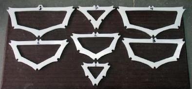
I completely redesigned the waterlines; they should be as similar to the original baidarka as possible for a foldable version, which features only one stringer. The ''Nevermore'' is 5.16m long and has a beam of 55cm. At the time, I can only provide you with sketches of the most important parts, especially the four ''gunwale spreader frames''. This is because the other frames are interpolated directly into the structure. You should check David Zimmerly's book; that's where I got the data from.
Anyhow, should you prefer building a wooden folding kayak, I would suggest talking to my brother who has built an extraordinary masterpiece of a folding Greenland Eskimo Kayak. I have enclosed several prints of his boat here.
The output of this action is a boat's beam, length, sheer and rigidity against vertical loads. Combined with the given height of any section, this also predefines the boat's amount of rocker. The two gunwales are designed so strong that they can accept all vertical loads that bear on the structure. This is done with two aluminum tubes and stiffening shear plates that creates an efficient and lightweight shear webbing. The next step is to set up the deck stringer and cockpit rim; now this defines a sort of a ''deck frame''. This approach's advantage is the simple building bed (you may just take some sawhorses); the aleuts also built the ''deck frame'' first. The height of the frames and the position of the stringer result out of David Zimmerlys book ''Qajaq: Kayaks of Siberia and Alaska'', page 17 (Aleut Kayak, collected on Atka Island in 1934 by M.Lantis).
If you consult an aluminum structural handbook you will find that compared to wood, aluminum is not necessarily lighter and stronger if you do not change the construction details. I added to the height of the gunwales and the height of the sheer. I designed only one stringer and placed it at about the middle of the two lower original stringers.
Resulting out of the reduction to 6 frames, the large cockpit, and all that Make-It-Foldable-Stuff there is not much left of the original design of a baidarka. Anyhow, for me it is important to realize the idea of such an old design, even if my realization of it is foldable and of aluminum.
The 3-dimensional form of the boat directly results out of the bending of the gunwale tubes, constrained by the already mentioned four gunwale spreaders. Out of this I measure the dimensions of each frame. There are four frames left to make; 2 for the front and 2 for aft. Actually, I cut them out of 2mm aluminum plates. After all, I disassemble the boat and reinforce all frames. I add the tube connectors and after that, I cut all tubes apart. After cutting, the 3-d form changes a bit, because of the changed material stiffness at the position of the connectors. The boat is cut in two areas; so each stringer has three parts. One separation point is before the cockpit, and the other aft of it. At the position of maximum bending moments (the cockpit area), there is no connector that can break. The bag for the parts is about 1.7m long, 0.25m wide and 0.35m high.
I keep receiving questions about making PVC skins and thus have re-edited my comments about it into a single file that is a little easier to read. Now you see a mix of four years old comments with very recent ones.
Questions and comments by others are printed in blue.
The images are clickable and lead to the full-size (original) pages.
[ Skin Material ]
[ Welding ]
[ Skinning Sequence ]
[ About Tape on a Final Skin ]
[ About Temporary Skins ]
[ Lacing Skins ]
[ George Dyson's Hypalon Skins ]
[ Thomas Yost's Hypalon Skins ]
[ Epilogue ]
In short, the idea about glueing PVC is to use lots of thinner (Acetone). I had to test the mixture several days and came out with that it is right when the thinned glue begins to run off the brush by itself. Then apply it minimal two times to both surfaces. After letting the glue get nearly dry, combine the two PVC parts and press them well for some minutes.
For the first prototype I sewed two strips of PVC onto a zipper
and glued these zipper strips at the middle of the deck piece. This feature
was as strange as convenient;
it eased assembly and loading of the boat.
With some grief I dropped this idea and the actual design now has hatches
instead of the zipper. These hatches serve the same purpose except that
it is a lot more difficult to assemble the boat. Also I do not have these
sponsons any more that had to stretch the skin.
Anyway, the www site of STAMOID is http://www.stamoid.com/stamoid or http://www.forbo.com and they have some property sheets about that specific skin material.
The skin comes in doublesided or singlesided PVC covering on a polyester fabric. singlesided weighs 280grams/square meter, doublesided is 430g/m2, tensile strength is better than 1200N over 5cm width.
The singlesided stuff is covered with a dirt protecting finish, which makes glueing and welding impossible and thus has to be removed in the contact area.
Paul Raymond wrote: I stopped at a canvas store today, and he sold me 17 feet of double sided Stamoid for $100, which I think is a good price. Since this is for an aluminum folder, and Hendrik Maroske used it with success, hopefully I will too. I'll find another use for the pack cloth.
Stamoid is what I have used, it comes in both protected and unprotected versions. I suggest to get the thinnest material available, that is, I got the 0.6mm stuff and found it too heavy when glued together, so I talked my supplier into buying 0.5mm stuff for me. There even seems to be 0.4mm material out there, and a way to get material with defects (holes) in it (lots cheaper). This material is so thin compared to my Klepper, how does it hold up on your boats compared to commercial boats? Do you still prefer Stamoid to any other material available?
My most recent Baidarka still is the one from the 1999 Toronto trip. The Baidarka skin was finished late summer 1998 and I must confess I did not use the boat very much since Toronto. I have moved the workshop since, and with it the boat, and since that move the lake is a little more difficult to get to (without car).
Anyway, the pics on this website with several closeups of that particular skin have been made during Christmas holidays January 2002, so you have a guess at how good the skin actually is. It still looks "new enough", is tough as ever and still waterproof. No seams broke.
The skin is nearly four years old, the "unprotected" Stamoid, and ready to go on any trip. I'm satisfied with it. Always cleaned stains before they could wear in (with water only), because without the protection I am afraid to use chemicals to clean the skin.
I see that Tom Yost used polyester material, and then coated with hypalon, which worked well for him, but I wanted to avoid having to use toxic coatings, and the pvc material seemed quicker to skin.
To each one his way looks as the best afterwards. But I would still do it again. It took some time to learn to use a good balance of techniques, stitching, glueing, welding. Basically, my experience with Stamoid and Pattex and Acetone is that if the glue doesn't hold within the first five minutes, it never will. Throw away the pieces that you can and restart. If it holds, it always will. And by "holds" I mean you rip the pieces apart and not the glue fails, but the Stamoid goes apart.
Practice good bonds before doing the skin.
And even more basically the only advice I can give is to really do a few practice runs on the stem and stern pieces with the intention to keep them as samples. This will pay out in the end. Use double sided tape for the first practice run to have a good chance to rearrange things and if you don't want to wait for the glue to settle.
And, talking about abrasion, I cut Stamoid in strips and these were formed with a heat gun to match the curving of the hull before glueing them on over the stringers and where the skin pieces meet.
Generally the heat gun helps a lot to smooth out the results. Afterwards, the warm material is perfectly dry for glueing. It seems that there is some amount of (water or other) thinner in the skin that works against a good bond. Seems to be the stuff that makes the PVC soft.
There's different stuff available for glueing non-rubber zodiacs. 2-Komponent and stays flexible, although quite expensive
Welding is used only in professional applications for truck and tent awnings. I got caught by approximately 3mm material shink per meter as I welded the 5 seams in my hull. Makes funny waves in each section. Took me some time with my heatgun to shrink the whole skin, to take the worst away. :-(
Amateur tools for welding soft PVC without glue, just fabric on fabric, are air guns or the like. Their actual use and temperature operation range seem to fit. Use a rubber wheel on a stick to press the layers together. When it becomes black it's too hot... The professional heatgun that I used only melted the pvc surface without allowing for sticking. Something obviously wrong in my procedure. Welding was Gerald's idea, and for him it worked. My (Hendriks) heat gun did cause some degree of sticking, but not enough to really call this welding. It depends very much on the quality of the skin. If there is anything like "abrasive protection" or "dirt protection" put on it, forget about welding. What becomes black ?? PVC does not seem to change any colour. Is it the glue?? I guess that Gerald was joking. My white PVC just got darker and started fuming. Then it's time to rapidly stop heating. Final question not yet answered: do you stitch only for keeping the pieces together ? In other words, does the skin in its final version rely only on glue lines or is it glued and sewn. I could not really get this out of your description in previous postings.
In my case, stitching was used until the glue bonded permanently. After that time (some 15 minutes), the seams were removed where possible.
All your help is precious: I have just bought wallpaper and a range of water based markers to start the skinning job.
I got the wallpaper trick from Gerald, and it's worth it. You'll easily see how it will be with the PVC, since PVC doesn't have much more stretch than the wallpaper.
One thing about heat gunning:
I never was able to really shrink the skin. It's more like
rearranging it to stress, so that folds and waves remove
themselves. If you would really _stretch_ it with heat,
it will cool off and then be over-stressed and floppy.
So, I used the heat gun only for aesthetic corrections,
not for shrinkage.
Paul Raymond wrote:
Has anyone else had any luck using pack cloth, which comes coated one
side and dyed, and adding additional polyurethane?
Michael Daly wrote:
I have never tried, but wouldn't bother. Coated pack cloth, in addition
to having a urethane coating on one side, has a durable water repellent
coating on the fabric as well. The purpose of the latter is to prevent water
absorbsion into the thread and so enhance its waterproof properties.
I'm willing to bet this coating is what prevents a good bond with the
subsequent polyurethane coatings you apply. You need an uncoated fabric to begin
with, or at least one that has only a "coating-friendly" treatment applied.
Preventing any good bond, exactly. I had oversensitized my right thumb from rubbing the material with Acetone to remove the protection from the glue areas. Definitely NOT the way to go. Although the coating really is good, waterproof and repelling dirt.
Stefano Moretti wrote:
I need much help from more experienced skinners. This will be my first
attempt. I've finished the frame od the foldable with much satisfaction. It is
not wobbly as when I first started.
Congratulations! Now proceed to game level 2 :-)
1) Make hull and sides from one single piece, cutting "V" shaped slots in bow and stern. Seen this picture in FOLBOT virtual company tour.
No way. I also tried this. It is better to do it right, from the start on. Buy a roll of wallpaper and make cutting patterns. Cut the patterns in stripes following the chines, guns and keel.
2) Overlap hull and deck skin over the gunwale chine by more than one inch
Again, its better to go right through it: begin with a large overlap for sewing and then cut it small before glueing. The skin is not easily folded with such thick glue strips.
From my experience, I consider everything too thick that is overlapping more than 3/4 inch or has more than two parts overlapping at the same area
3) cutting deck from mid cockpit to bow, and from mid cockipt to stern, so to reduce the wrinkles and dragging all error towards the cockpit area where the big hole would accomodate much wrinkling. Done this with 3 mm plywood in clc kayaks, should work.
The less glue strips (rsp. easier folding), the better. If you go without deck ridge, there's no need to go with the deck seam. Always proceed to the ends rather than towards the cockpit. Otherwise, you end up having a slack skin at the cockpit.
4) for all unexpected problems and some extra stiffness (still very much debated I know) I would add two small section sponsons just below gunwale.
In my case, both designs worked well. Especially with cold, wet skin, sponsons give you the chance to re-stretch it.
How do you cut and glue around the Aleut stern.
Making these end pieces helps a lot in acquiring the skills to work with PVC. Throw away a piece if you are not satisfied. The next one will come together a lot quicker.
Having made a pair of useful end pieces, the large skin panels are glued over the end pieces, and when all the skin is done I add a nice looking finishing layer over the end pieces, smooting out the curvature and hiding all the seams, glued patches and the rugged connection between skin and end piece.
After having made the skin, I rip out the innermost PVC layer of the end pieces, thereby ensuring that the stem and stern will always slide into them without too much trouble. So, the very first PVC layer for these pieces is attached only very temporarily, with double sided tape or masking tape.
Do your PVC skins have a seperate panel for each Keel to chine, Chine to gunwale, and gunwale to deckridge, or are you able to cover greater areas at once?
Greater areas simplify nothing. They make things more complicated, and if something goes wrong, you'll have to throw away more skin. My boats have fairly high gunwales, more like 'planks'. The sequence is like this ( I began inside-out, here's a sketch, but that is not absolutely necessary):
What weight PVC would you recommend ?
The thinnest/lightest you can get. I have used .6mm thick stuff and next time will definitely use .4mm instead. Because every seam doubles the thickness, and together with the glue it really gets stiff. If you expect trouble somewhere, use the thinnest stuff you can get and apply strips wherever needed. The procedure for the stem/stern I described yields very stiff results.
From now on I assume that you have made a set of good end pieces and are ready to skin. PLEASE, use wallpaper for making cutting templates. Cut strips aligning to chines, guns and keel. (in my case, 6 strips + 1 deck strip). By any means make strips the whole length of the boat. Leave out cockpit rim.
On the inverted hull, sew together the two strips that meet at the keel and go up to the chine stringer.
Sew strips loosely together using 1 inch spacing between seam stitches. Sew only where PVC is cut away anyway. This routine worked best for my Greenland Baidarka with only one chine stringer and the gunwales having an upper and a lower stringer.
I used a twohole punch to make a row of holes at a long side of a large piece of PVC and temporarily sewed it directly onto the frame prior to glueing it to other pieces. This way I could reduce the count of folds in the skin.
Sew the two strips that go from guns to chine to the ones you just sewed together, leaving off the stripe between lower gunwale and chine and thus using large seams over the hole (stitches 5-7cm apart).
Loosely attach the previous mentioned strips to the guns (stapling them on wood frames, using tape on aluminum) and rotate the hull
Sew on the deck strips with a rough seam, stiches some 3cm apart
Use heat gun to remove wrinkles everywhere. Rotate hull.
Use heat gun to stick (weld) the remaining two strips to their place between the lower guns and chine stringer.
Remove the large seams under the two newly attached strips. Use heat gun to partially lift off those strips and reattach them without wrinkles.
Lift one yard of each strip, clean contact area thoroughly, apply "hendrix mixture" and glue them together. Make sure glue line is only 1.5 - 2cm wide. Glueing procedure described later. Work towards the ends of the hull, cleaning and glueing.
Let the glue dry. Cut excess skin at the newly made joints.
Use heat gun to remove wrinkles. Do not generate excessive heat at the glue strips!
Redo the keel seam (the butt type, not overlapping!). Now space the stitches 1cm apart. Cut excess skin. Now the borders of the two skin strips just touch each other.
Use heat gun to remove wrinkles at keel area. Cut keel strip (3cm wide) and lay it over the keel. Use heat gun to smooth it over the keel's curvature.
Remove keel strip, clean keel line, 1.5cm in each side (=3cm wide total).
Remove keel seam for two foot length, glue the keel strip where the seam was, to make it watertight.
Redo gunwale seam. Proceed as with keel.
Glue small horizontal skin strips over the bow and stern to generate the Baidarka's extremities. For Greenland Kayaks, much less work since larger patches usable.
Cut and seal the cockpit area.
Don't forget to make sure there is no "protective impregnation" of some sort over the PVC. Otherwise, you get lots of additional work to clean the glueing areas.
Be meticulous at the cleaning operations.
Always make test specimens and rip them apart to see whether the glue mixture and/or cleaning operation was successful.
Well, "hendrix mixture" goes like this:
- thin the glue until it quickly runs off the brush by itself.
- thoroughly mix
- apply three times, let dry after each application
- contact the parts
My glue is the German "Pattex Transparent", thinned with Acetone. You might want to ask my brother Gerald, who is a chemistry professional, what the american equivalent is.
I put a rub strip over every seam and have had good results.
In my first attempts, I also have put rub strips inside the skin; this is not so good, since skin folds less easy, is more heavy and tends to develop folds. Also I simply cannot glue well on the frame from the inside.
On my first foldable Baidarka, the double sided tape that had to closepart of the deck seam and seal it watertight, became an ugly black smeary, slimy thread after a two-week saltwater session. I'll never do this again...
Now, it seems that most of us just try with the expensive skin (me included), ignoring the possibilities of tape (although I tape virtually everything) and clear plastic. I just always had tried to avoid the additional work involved.
But that can be real fun; here is an account of what can be achieved, if you really want.
Tom writes:
This temporary folding skin is made of PVC to test the
viability of the material as a one piece hull.
In this test, I've pulled the skin fairly tight using
squidding line but am careful not to
over stretch. There are still a few wrinkles in the
skin, but to this point no heat has
been applied. The "Real" skin will be made of higher
quality, thinner, Stamoid PVC.
This is a good picture. I have seen this quite often with my own first PVC skins.
My own experience at working with very large PVC skin panels is that bulges develop at the few remaining seams which show that the skin doesn't fit closely. These bulges were quite sharp since in the other places the skin would fit very smooth. Afterwards it was impossible to remove these bulges.
If you look closely, you will see the vertical folds in between the gunwales and stringers. This is exactly the problem zone, they tend to concentrate right before and after the cockpit. On the other hand, the keel area looks good... how about a single piece for both keel panels? Now, the keel needs a rub strip anyway, so there is also no real advantage in doing it in one piece. Doing it in two pieces yields much smoother stem and stern parts. You will find that narrow PVC panels are much easier to work into a pre defined shape.
My own conclusion is that a one-piece skin is perfect for testing the frame before doing the final skin. This one took less than three hours to make. Very motivating.
Tom writes:
The Stamoid has unidirectional fibers which would only conform
in one direction, so it wouldn't take the shape of the hull
without getting all wrinkled at the stringers. In addition, and
the thing that bothered me the most, was the fact that the Stamoid was easy to tear when I
pulled on the stitching that I used to stretch the skin. This
happened in only one direction , parallel to the fibers.
I've never had a skin material
tear before, so it really caused me concern.
I still feel that a one piece PVC hull is workable, as it has been
done by others. The problem I had was trying to do it with Stamoid.
The black PVC had
multidirectional cloth , the same that I use on my sewn skins, so it had
the ability to conform to the stringers. I didn't have enough of it for
the entire boat so I
purchased Stamoid thinking it was made the same way. It wasn't.
About the Stamoid tearing easily when sewn; that is a good point. If I recall correctly, the thicker 0.6mm variant would not tear as easy as the 0.4mm one. Anyway, I had no other comparison and was satisfied with the 0.6mm stuff. Although I have never seen a skin tear on my boats, even on tar or stone beaches. And back then I simply took it as normal, but shame on me, I have used only a small amount of really thin Stamoid, mostly using the 0.6mm material. I stand corrected in having said the thinner material is better. Maybe the thicker material has a stronger cross weave respectively more cross weave?
Here is what I found today, 28OCT2002 when measuring the tearing resistance with a thin line that I would use for sewing the skin (25kg test Dacron). I punched the "sewing" holes an inch from the border and an inch apart:
Direction crosswise to roll length (in roll axis):
20kg,18kg22kg (average=20kg)
Direction following roll length, that is, the fibers,
if fabric were of unidirectional fibers:
12kg,14kg,20kg (average=15kg)
To me the difference doesn't look so alarming, but yes the Stamoid actually is not at all multi/bi directional.
During my boat building runs I noted a rather large variation in quality even in a single roll. Also, the material sample I just have tested is 0.55mm thick instead of the supposed 0.6mm. The resistance to tearing with a strong line also varied a lot and was kept at bay in using a small distance between stitches. In the end I glued everything anyway. Also I used to use a thinner, weaker 10kg line that would rupture before the skin would tear and would not interfere with glueing.
I never could achieve anything with "lots" of heat shrinking on Stamoid. Only with narrow strips that were formed with the heat gun. Heat only re-aligned the weave within the PVC very lightly.
I also have heard of several people trying a one-piece skin, but my own results were frustrating (see above). See here for Patrick Poirier's results.
I know several people who have used hypalon on folding skins and I haven't heard complaints. Of course, commercial folding kayaks and most inflatable boats also use hypalon coatings, but those are impregnated under pressure and thus bonded more completely. But it is a good sign that the river rafting industry has stuck with hypalon for at least 20 years.
I should have all kinds of free time since I finished my new book, but I still haven't found time to revive the BHS. Fortunately, the skin boat revival has a life of its own, and is doing fine.
There's an excerpt of my new book, with discussion, at:
best wishes,
George B. Dyson
Click here for a
view of a Thomas Yost's design for a folding Hypalon skin.
Click here for a
view of a very easy method of lacing the skin to the frame.
"what's that"
I answered "my boat".
"a boat?"
"yes. It's a Baidarka." Having said that I thought he'll ask something about what a Baidarka is. Especially some question about that bow. Instead came
"why'd you wrap your boat in plastic?"
Construction Details.
You should try to avoid round tubular aluminum stock; although George Dyson is
very fond of that, it does not make much sense for a foldable construction
(Here is a better solution).
This is because in a foldable boat, there are few occasions to lash tubular
components and seal the lashings with epoxy. Instead, I am using aluminum
rivets that can be drilled out again and change the most important rivets
to stainless steel type or to a larger diameter when I am done with the
boat.
Riveting tubular material is difficult; at the time I was using the stock I have bought four years ago and when I am done with that, I will buy rectangular material with rounded edges. Stuff like this definitely exists, and I have some of it. The optimal material, from my point of view, seems to be the high-tension 25mm x15mm rectangular tube with a wall thickness of 2mm. It is a little small though, but I hope it can easily be riveted and so joined with aluminum plates. If not, I'll try the larger versions. Those joints are necessary at any locations where the pieces of the boat need to be easily separatable.
The new design has only four stainless steel screws at places, where everything else seemed inconvenient enough for me to admit additional tools for assembling the boat. Usually, I do not take the boat apart; the only (and important) time that I did this was on the trips to Canada and Norway. And then, I had the time to fix all those screws. Here in Germany, for example, I do not take bow and stern apart; I have the space to store and carry them assembled, because the Lake of Constance is just a short walk away.
The design makes limited use of those stainless steel pins, that you can buy at sailor's shops and that need a round, springy splint to prevent them from falling out of their hole. At convenient locations, the two stringers and the keelson are simply riveted together. This creates some large parts, larger as the gunwale parts. But size was no problem on our trip; more important was weight, and that stays the same. The idea of this is to create a few, large but rigid components that can easily be disassembled and that have no weak joints at locations of maximum stress.
I did all the cutting of the aluminum plates with a band saw, and that really is noisy. Expect your neighbors to make trouble if you cannot access some factory or remote workshop. The next big task was glueing the PVC skin. My brother sewed the deck parts of cotton; this reduces the amount of toxic fumes in the workshop.
Apropos workshop: mine was at times my garage, and that's why I am fond of these sawhorses as a building bed. I push the car out of the garage, take the boat off the wall and put it onto those sawhorses. Later in the evening, the garage may resume its function within minutes. To prevent sharp aluminum parts or the pins of the pop rivets puncturing the tires, and to protect new PVC skins from getting oily, I have laid an old carpet on the garage floor which I remove after usage.
Another detail are the strips of used bicycle tire that I have sewed onto strips of PVC and then glued onto the keelson at the bow and stern. The idea is to reduce abrasion of the skin. This does a good job especially when I carry the boat on wheels.
There are better descriptions of how to build a baidarka; the following are available online:
I haven't tried it yet. Just looks like a very good idea. In Germany, you'll get this at http://www.wmh.de. The important fact presented here is, there is something better than round tubing, because with the above we can easily attach fasteners to otherwise round tubes.
The 50x20mm and 36x16mm stuff looks promising. It is AlMgSi0.5 which is similar to 6060 quality, the material is used in sailboat masts. Try it sometime.
That's why it is called Last Chance.
Added above are sketches of what we can obtain here in Germany at a Hang Glider manufacturer/supplier. Does anybody have an address of a supplier in the USA or Canada? The German address is here, but doesn't show the parts anymore. Maybe they are in their paper catalogue.
Good tools on every trip. Especially the fishing guide is worth reading.
We move easily, unafraid of what lies below because we ourselves have created above. Our craft forged by our hands, dreamed into existence by our hearts.
This is why we are here. This is who we are.
This wildness. This earth.
These hands. This heart.
This life.
My life.
Unfolding across the infinite span of creation and experience.
Earth, hands and heart pulsating in unison.
Contributed by Ken Lalonde
Edmonton; Alberta, Canada
There are colored
buttons under the top image:
Previous Slide
Up to the Index
Design Page
Introduction and Overview
Next.
Now switch to the next page (click the image).
Let's go then.
Have fun!
People often ask me that question, and I still have nothing useful to throw at them as a one-shot answer. Especially because it only makes a lot of work. But that bow is an important part of the picture I had in the very first place after reading George Dyson's book: I saw myself sailing an aluminum Baidarka along some part of the Inside Passage. What kept me going full power through all these years was that picture. Then a lot of help from my brother Gerald made it come true; he also took the right photo at the right time, and now it occupies some 2x3 foot on my workshop wall...
[Forewords:]
[Why the Funny Bow]
[Skin-On-Frame Aircraft]
[Baidarkas and Aircraft]
Kayak Design Page:
[Frame Joints],
[PVC Skin],
[Measurements],
[First Disassembly]
[Baidarkas]
[Greenlanders]
[George Dyson]
[´91]
[´92]
[Trip´95]
[Trip´97]
[SaU´97]
[Trip´99]
[Get Going!]
[Contributors]
[Baidarkas and Aircraft]
[Transport]
[Toms Kayak Bag]
[Motorcycles]
[Surfing Vancouver Island]
[Fishing]
[Camping]
[Sailing Tent]
Design
[NEW: Tom Yost: FAP-15 and SPY-10]
TDY-16F]
[Pat Poirier]
[Aleut Paddles]
[Folding Greenland Baidarka: Detailed, Animated Assembly]
[Design of
Folding Aluminum or Wooden Baidarkas and Greenlanders: Parts;
Construction; Assembly Stages]
Thomas Yost:
[SPY-10]
[FAP-15]
[TDY-16F]
[FAP-16]
[BIF-16]
[feather]
[Dyson Double]
[CNM-12212]
[MAE 593-76]
[LM 2-14886]
[David Hazen]
[Dyson Single]
Gerald Maroske:
[West Greenland]
Hendrik Maroske:
[Lost Soul]
[Nevermore]
[Last Chance]
[Inside Passage]
Roy Clo Baggerly:
[Twelve!]
Photos:
[Baidarkas]
[Kodiak 3-Hatch]
[Greenlander]
[Expo 67]
[Dyson's 3-Hatch]
[Dyson's 737]
[Unknown]
Design Info:
[Aluminum Construction]
[PVC Skin]
[Wood Construction]
[Comments]
[Oval Tubing]
[Measurements]
[Workbench]
[Gail Ferris]
[Kayak Cart]
[Text Only]
[File Access]
The [Text Only] index has all text in one huge page (no slides, only embedded pics).
The  Page Index
table helps you find pages you haven't seen yet.
Page Index
table helps you find pages you haven't seen yet.
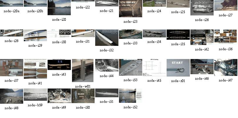

|

|
All this, including high resolution pictures and animations,
the Baidarka mail archive and
several other web sites is distributed by
Charles Hall. Visitors from Europe can also order here for production cost.
|
|
Greenland Paddling | Here is an article about Greenland paddling technique by Greg Stamer. Greg describes his lessons lerned from Maligiaq Padilla, the Greenland National Kayak Champion. |
Skin-on-frame airplanes...
But what started me into the whole paddling business was this Oregon Coast trip in 1992.
This slide show is about Baidarkas. But with a bias towards folding boats and Greenland style kayaks. ''Baidarka'' is a russian word for ''small boat'' which got used not only for Aleut kayaks but especially for Kodiak kayaks which differ noticeably in construction.
This project was initiated by George Dyson's book ''Baidarka''. I consider George Dyson´s three-man kodiak Baidarkas to be his most inspiring work, together with the part of the book that treats their history.
But what got me started into the Baidarka thing in the first place, is the nice connection he made between Boeing aircraft, aluminum tubing, scrap yards and modern Baidarkas. That's why I chose the pic with the airframe and Baidarka for this page; my interpretation of the theme has always an aircraft bias towards it. If I cannot build an aircraft due to the huge amount of time, money and experience necessary, the next best thing to build is a Baidarka. I took up the construction of five Baidarkas as a means of gaining experience for making an aircraft. Especially the three folders helped in learning to take matters more seriously.
It seems that others share the same motivation, for an example take a look here, Or take a look at Geralds kayak parts, although maybe not intentionally, they somewhat look like airplane parts as well. My own construcion in comparison somewhat looks like a tank or gun (better than the furniture I made, it all looks like coffins), and the construction was nearly as much effort as a assembling a small airplane kit.
Also, with a folding kayak, I was depending upon airlines a few times for transportation. This is a good place to return the favor I received from the friendly folks there.
These pages also contain travel pics, shown from the perspective of someone carrying around 120 to 140 pounds of gear per person...
When you take it apart does it become a kit?
Well, yes. My first designs took several hours to assemble. Now I am somewhere at under an hour assembly time. But basically, my folding Greenland Baidarka still is somewhat of a construction kit.
But that is no real problem. My own design assembles a lot better than the two-place folder I have bought. Joints are a lot more precise and rigid, and the overall stability of my frame is worlds apart from that of the commercial product. So it definitely is worth the extra effort at assembling the Baidarka. At least, there is no commercially available folding Baidarka, and I think I know why. I designed my foldables against the structural strength of a rigid Baidarka. Problem is, I only have had two rigid aluminum designs of my own deviation from George Dyson's. This deviation makes it difficult to give absolute numbers.
Here is more on frame stiffness measurements.
Now that I have made a wooden foldable Baidarka, I can tell that my very first aluminum designs were a lot less flexible than this wooden version. This was due to my usage of tubing with very large outside diameter (20mm). Using 18mm tubing should give better results. Using thin-walled tubing will have the problem associated with it that during transport the tubes will get bent and dented.
Anyway. The Aleuts fixed their gunwales into the stem and stern deadwood and made sure they would not move within these joints. Gerald and I simply kept to this rule and made sure that all the foldable longitudinals are thoroughly interlocked to prevent them from changing their length, no matter how thick or thin they are. This was a major design problem for us since anything that interlocks is an attraction spot for salt water. This tends to transform a folder into a partly rigid boat that defends itself from being disassembled (as mentioned in Gerald's "bloody fingers" mail).
And don't forget the skin. A good part of the stiffness of the boat is due to the tension of the skin - it limits the motion of loosely assembled parts.
That's why it is called Last Chance.
In this my first folding design, a very loosely fitting skin was laced over a very loose frame. One could forget about the skin's contribution to frame stability; in my case, this worked only in theory. Maybe this is due to actually very small loads, I don't know. Here are measurements that seem to point in the same direction.
However, some parts of that frame were put loosely together for my inability to do a better design. Some parts even had some sort of interlock that I had to cut away to be able to assemble the boat. In essence, being outdoors gave nature a great chance to get me streamlining my assembly procedure.
But it was amazing what loads and abuse that frame was able to bear. This surely is good news for any newcomer. At least in my case even that first design was well good enough to do the job.
Some of the slides are large animated GIF movies. To reduce load time I have cut the assembly process into parts. Just keep in mind that the assembly happens within the skin, but is shown without the skin for clearance.
This whole shebang is available on a CDROM, including several other web sites. It is made by Charles Hall and distributed for production cost.
The animated assembly movies of LostSoul:
With this design I wanted to reduce the height of the deck stringers. I always wondered if the one-hatch Baidarka deck design really is the big thing, partly because I am making foldable Baidarkas:
Surely the Aleut people had their ways to cope with that, but I was struggling to make my craft seaworthy. According to today's accepted safety standards. I had to change it in order to get a foldable design, and the result is very similar to the Greenlanders, especially since the waterlines of my folding kayaks come close anyway.
Well, this looks like something. I made a good rear hatch, with the pump installed and everything, skipped that rear deck stringer and now have a nicely fitting tilted cockpit. Seems like progress.
Here is what others have said about my modifications to the Aleut design.
In order to save weight, TDY-16 is built using 3/4in X 0.035 tubing. In addition, there are 6 HDPE cross sections (FAP-16 has seven). The HDPE stem/stern use lightening holes, and the coaming will be light weight fiberglass. The frame, without coaming, weighs 13.5lbs. Completed weight with 13oz. PVC skin material should be approx. 25 lbs.
LOA - 16ft.
Beam - 23in.
Weight - 25 lbs.
Stringers - Aluminum 3/4in. X .035 Walls
Skin - PVC
This Non-Aleut design is intended as a lightweight medium volume touring kayak. As compared to FAP-16, it features a peaked deck to improve interior room for the paddler as well as more storage space. It utilizes thinner walled tubing (3/4" X .035) and six cross sections ( FAP-16 has seven) to reduce weight. The cross sections, coaming, and footbrace are made from HDPE. Finished weight is approx. 26 lbs.
The skin is a sewn, one-piece Polyester (9 oz.) design, and is coated with Neoprene/Hypalon. The hull is covered with eight coats of neoprene, while the deck is covered with five coats neoprene and three coats Hypalon. Neoprene is a bit easier to apply than Hypalon. It cures quicker, and is more durable. Hypalon has the advantage of being easier to fold, and is available in many different colors.
The following pages highlight only those construction details not included with, or that differ from FAP-16:
Stem, Stern and Frame
FAP-16 and TDY-16 Frames
TDY-16 Frame
Coaming Details
The HDPE coaming is comprised of 1/4" baseplate, 1/2" coaming, and 1/8" coaming lip.
Machine screws are used to provide a secure coaming attachment.
Polyester Skin (9oz.)
The one-piece Polyester skin is sewn with nylon squidding line.
The deckridge and stem/stern are cut (seared)
with a propane cutting blade prior to sewing. This process
assures a hard edge that will not separate.
The deckridge will be cut open for the installation of lacing or zippers.
Neoprene
The frame is first waxed to insure that neoprene will
not soak through and stick to either the aluminum or HDPE.
Before coating , a heat gun is used to remove wrinkles
still remaining in the skin after sewing.
The first two coats of Neoprene are thinned with 10percent
Zylene to insure that the neoprene will soak deeply
into the polyester cloth. Subsequent coats are thinned
but to a lesser degree.
Neoprene is applied with a 3 or 4 inch brush. Use short brush strokes and be sure not to brush the neoprene once it starts to glaze over. That will cause ripples in the surface. Maintain a wet edge and move quickly along the surface. Subsequent coats of neoprene can be applied every 30 minutes or so.
When the skin is removed, the inside hull will receive 2 additional neoprene coats. This is not necessary, but will insure complete saturation, and makes for a better looking job.
Always wear a respirator, and work in a VERY well ventilated area.
Hypalon
After applying neoprene, the deck or hull can be coated with
additional Hypalon to give it a color other than black.
Hypalon cures slower than neoprene and requires a longer
wait between coats. Hypalon stays slightly tacky
for a few weeks. Adding Lacing, zippers, flaps, and deck
rigging can be done in a week or so after coating.
Wait several weeks after coating before removing the skin.
I normally wait a couple of months before folding the skin.
The main advantage of the Polyester/Neoprene/Hypalon skins are their one-piece construction and ease of repair. An additional coat of Neoprene/Hypalon every couple of years will keep it looking like new.
Rub strips can be glued to the keel and chines for added durability.
Skin/Coaming Attachment
On FAP-16, the skin to coaming attachment is accomplished
by wrapping the skin under the baseplate and using snap connectors
(see here for the idea).
On TDY-16, the skin is attached directly under the coaming with machine screws and recessed snap connectors. This is a cleaner installation, but the other method is easier.
Finish
At this stage, all that is left is to install lacing or
zippers, attach the flap, and deck rigging.
The seat is a gunwale mounted sling type similar to that
in FAP-16. A paddling report will be added later.
The cross sections, backrest and footbrace are made of HDPE. The skin is a sewn, one-piece Polyester design. Coating are Neoprene/Hypalon.
The deckridge is considerably taller than FAP-16 to provide greater room for comfort and storage. Personally, I prefer lower, flatter decks, but wanted to provide an alternative for other builders. This Aleut based frame is made of 5/8" tubing. Though flexible, it showed no signs of deflection in the water. The HDPE cross sections allow for ease of construction and assembly. The tubing size and number of cross sections are the same as the Feathercraft Kahuna (14'6" LOA). Tubing size can be changed to 3/4" if desired during construction.
The design goals for FAP-16 were to make the kayak easy to build (Under 100 hrs.), Easy to Assemble (Under 30 Min.), and light weight (under 40lbs). Above all, Tom wanted this boat to perform as well as any non folding skin kayak.
LOA - 15ft. 8in.
Beam - 23in.
Weight - 35 lbs.
Stringers - Aluminum 3/4in. X .049 Walls
Skin - Polyester/Hypalon
LOA - 16ft 2in.
Beam - 20.5
Weight - 25lbs.
Construction Time - 75hrs.
Tom writes:
I've just recently completed a new kayak after a few years inactivity. The design is a hard-chine Iqyax (CNM-12212) that I built based on a simplified version of George Dyson's method utilizing aluminum stringers with plywood cross-sections. The skin is 8oz nylon coated with several coats of neoprene/hypalon.
Length - 17.5 ft
Width - 17.5 in
Weight - 28 lbs.
Cp - .61
Tom has built approximately 16 boats since 1975, with the first eight being woodstrip/fiberglass sea kayaks. Of that group, two have been Aleut designs constructed from David Zimmerly's offsets in his book "QAJAQ". He built them to scale but made changes to the deck shape. In addition, Tom built a woodstrip version of George Dysons double .
Having grown a bit tired of building woodstrips, he decided to try a hand at non folding skin boats. He first made three George Dyson singles, the first two of all wood construction, and the third using wood cross sections with aluminum stringers.
He immediately realized that these were more seaworthy than were the woodstrip hulls. The flex in the skin and the concave skin shape between stringers, really slowed down the roll rate as well as allowing the hull to conform to the waves.
The first folder that Tom has made, about 1993 or 94, is a folding wooden (pine) version of a Dyson single. Skin is Nylon/Neoprene/Hypalon. Time to assemble - Forever !
His second folder was an
Aluminum/Wood Dyson Double (1996).
Third was an Aluminum/Wood single (1997).
Fourth was an Aluminum/HDPE single- FAP-16(2002)
Fifth is an Aluminum/HDPE single - TDY-16(2002).
Sixth is an Aluminum/HDPE single - TDY-15(2002).
Above is a photo of the folding single that Tom was building 1998(?). You will notice a striking similarity to the "Feathercraft" designs. Since he paddles a Feathercraft K-Light, the similarity is no accident. You will also notice that there are very few parts. This boat follows the KISS principal. ( Keep It Simple Stupid)!
The tubing is all 3/4 in. Aluminum 6061/T6 thin wall. The tubes are attached to the Cross sections using "L" shaped brackets pop riveted to the tubes. The frame weighs about 15 lbs and takes only a few minutes to assemble. The frame has a single stretcher bar at the keel. The skin will be made of 14 oz. pre-shrunk nylon. The material will be coated inside and out with three coats of black Neoprene. The deck will receive additional coats of white hypalon to provide a light color. The boat is 15.5 ft (4.73m) long by 24 in. (61cm) wide.
Tom plans to use zippers along the deck ridge for closure and sewn in sponsons to assure a tight fit and to provide additional stability.
At least in my case, the zipper/sponsons solution has worked more than once. Just take care.
They keep getting lighter, easier to build, and quicker to assemble.
The frame contains four sections which are joined by metal joints.
Total length of the kayak is 5.35m and width is 52cm. It weighs 20kg.
The fore and aft sections are assembled separately. The two middle frames are inserted after stringers and keel are joined inside the hull.
The frames are made of seven-layered, nine millimeter birch plywood except the two main
frames in the middle, which are doubled to 18mm.
The massive parts are all ash and the gunwales/1st chines
are stiffened by 3mm 6-layered birch
plywood.
The joints are made of aluminium and stainless steel parts and all screws are made of stainless steel. Most nuts used are selflocked. All joints are handmade. The joints for the keel and the joints separating the fore and aft sections are tightened by hexagon screws. All other joints are assembled without tools.
The skin is polyester-reinforced-PVC (truck cover) for the hull and cotton/polyester for the deck. The hull is made of 3 parts each side (~36m to sew) but the deck is one piece. The inside of the deck is sealed with a layer of silicone (used for sealing windows etc.).
Assembling starts with the rear section inserted first. This is done because the cockpit coaming is installed with an angle, which provides a better in and out and this is valid both for paddler and framework. A special tightener is used to pull the keelparts apart and stretch the skin. When the keel is joined, both gunwale-joints are also pulled apart one-by-one and joined. The stringers are now joined easily. The last two frames are inserted starting with frame No.4 (backrest) and then No.3 (kneeframe or masik). When this is done the deck stringers are inserted and the last thing is to attach is the cockpit-coaming (steam-bent out of two parts, lip and ring are both ash of 1cm thickness, for a procedure look at Chris Cunningham's article "Building a greenland kayak" in the 'Seakayaker' magazine).
Assembly time is 35 minutes for me (Gerald).
This is the nicest folding Kayak I have seen so far (Hendrik), the joinery is a dream:
Stern Joinery
Frame and Gunwale Joinery
Gunwales
Design Sketch
Here is Gerald's original page with more info on his design.
And here are all available pages:
Patrick built his kayak in his living room. He plotted the sections
to scale 1:1 and glued them on 4x4ft baltic birch sheet. That's why
you see white paper on section backs.
Patrick has used a small brass hinge to connect the cockpit halves.
The skin is black and yellow PVC coated polyester mesh 16 OZ, 0.5 mm thick bought
in a truck tarpaulin maker shop. For 100$ CAN he got all needed
fabrics plus a quart of HH-66 vinyl glue.
When Pat has created the DXF the view scale was "1"
so normally when you will print on
a plotter the scale will be ok. But not all plotters
can print that size of paper so to use it
you have to divide in four equal parts and separate
in four different files. Don't forget that little detail.
On vacation in August 2002 Pat went with his friend in their
chalet on the shore of the small lake Dubuc in deep wood on
Mont-Valin a chain of mountain in the north of
Sagnenay river. He is from Jonquiere, a small city of sagnenay
region and brought the kayak with him. First real trial
while fishing rainbow trout and being by mosquito's!
Pat's hull design is made of four parts. Separation approx 1-1/2
feet after stem and stern and one separation in the middle.
He removed all the wrinkles with an iron set to medium
and a cotton shop towel to avoid sticking. This works as well as with a heat gun.
Based upon my own experience, wooden sections are preferable
over aluminum sections because they don't deteriorate
so fast (bending, buckling, denting). HDPE is even more
versatile, but considerably heavier than wood. All in all,
a really good design, especially for the first one you do.
At the left is a pic of a new used hockey bag with all the kayak in it.
Like you see on the pic there is a little measurement error but it is the
perfect bag.
Push and Secure
Pull and Secure
Rotate and Lock
This and That
I keep receiving questions about making PVC skins and thus have re-edited my comments about it into a single file that is a little easier to read. Now you see a mix of four years old comments with very recent ones.
Questions and comments by others are printed in blue.
The images are clickable and lead to the full-size (original) pages.
[ Skin Material ]
[ Welding ]
[ Skinning Sequence ]
[ About Tape on a Final Skin ]
[ About Temporary Skins ]
[ Lacing Skins ]
[ George Dyson's Hypalon Skins ]
[ Thomas Yost's Hypalon Skins ]
[ Epilogue ]
In short, the idea about glueing PVC is to use lots of thinner (Acetone). I had to test the mixture several days and came out with that it is right when the thinned glue begins to run off the brush by itself. Then apply it minimal two times to both surfaces. After letting the glue get nearly dry, combine the two PVC parts and press them well for some minutes.
For the first prototype I sewed two strips of PVC onto a zipper
and glued these zipper strips at the middle of the deck piece. This feature
was as strange as convenient;
it eased assembly and loading of the boat.
With some grief I dropped this idea and the actual design now has hatches
instead of the zipper. These hatches serve the same purpose except that
it is a lot more difficult to assemble the boat. Also I do not have these
sponsons any more that had to stretch the skin.
Anyway, the www site of STAMOID is http://www.stamoid.com/stamoid or http://www.forbo.com and they have some property sheets about that specific skin material.
The skin comes in doublesided or singlesided PVC covering on a polyester fabric. singlesided weighs 280grams/square meter, doublesided is 430g/m2, tensile strength is better than 1200N over 5cm width.
The singlesided stuff is covered with a dirt protecting finish, which makes glueing and welding impossible and thus has to be removed in the contact area.
Paul Raymond wrote: I stopped at a canvas store today, and he sold me 17 feet of double sided Stamoid for $100, which I think is a good price. Since this is for an aluminum folder, and Hendrik Maroske used it with success, hopefully I will too. I'll find another use for the pack cloth.
Stamoid is what I have used, it comes in both protected and unprotected versions. I suggest to get the thinnest material available, that is, I got the 0.6mm stuff and found it too heavy when glued together, so I talked my supplier into buying 0.5mm stuff for me. There even seems to be 0.4mm material out there, and a way to get material with defects (holes) in it (lots cheaper). This material is so thin compared to my Klepper, how does it hold up on your boats compared to commercial boats? Do you still prefer Stamoid to any other material available?
My most recent Baidarka still is the one from the 1999 Toronto trip. The Baidarka skin was finished late summer 1998 and I must confess I did not use the boat very much since Toronto. I have moved the workshop since, and with it the boat, and since that move the lake is a little more difficult to get to (without car).
Anyway, the pics on this website with several closeups of that particular skin have been made during Christmas holidays January 2002, so you have a guess at how good the skin actually is. It still looks "new enough", is tough as ever and still waterproof. No seams broke.
The skin is nearly four years old, the "unprotected" Stamoid, and ready to go on any trip. I'm satisfied with it. Always cleaned stains before they could wear in (with water only), because without the protection I am afraid to use chemicals to clean the skin.
I see that Tom Yost used polyester material, and then coated with hypalon, which worked well for him, but I wanted to avoid having to use toxic coatings, and the pvc material seemed quicker to skin.
To each one his way looks as the best afterwards. But I would still do it again. It took some time to learn to use a good balance of techniques, stitching, glueing, welding. Basically, my experience with Stamoid and Pattex and Acetone is that if the glue doesn't hold within the first five minutes, it never will. Throw away the pieces that you can and restart. If it holds, it always will. And by "holds" I mean you rip the pieces apart and not the glue fails, but the Stamoid goes apart.
Practice good bonds before doing the skin.
And even more basically the only advice I can give is to really do a few practice runs on the stem and stern pieces with the intention to keep them as samples. This will pay out in the end. Use double sided tape for the first practice run to have a good chance to rearrange things and if you don't want to wait for the glue to settle.
And, talking about abrasion, I cut Stamoid in strips and these were formed with a heat gun to match the curving of the hull before glueing them on over the stringers and where the skin pieces meet.
Generally the heat gun helps a lot to smooth out the results. Afterwards, the warm material is perfectly dry for glueing. It seems that there is some amount of (water or other) thinner in the skin that works against a good bond. Seems to be the stuff that makes the PVC soft.
There's different stuff available for glueing non-rubber zodiacs. 2-Komponent and stays flexible, although quite expensive
Welding is used only in professional applications for truck and tent awnings. I got caught by approximately 3mm material shink per meter as I welded the 5 seams in my hull. Makes funny waves in each section. Took me some time with my heatgun to shrink the whole skin, to take the worst away. :-(
Amateur tools for welding soft PVC without glue, just fabric on fabric, are air guns or the like. Their actual use and temperature operation range seem to fit. Use a rubber wheel on a stick to press the layers together. When it becomes black it's too hot... The professional heatgun that I used only melted the pvc surface without allowing for sticking. Something obviously wrong in my procedure. Welding was Gerald's idea, and for him it worked. My (Hendriks) heat gun did cause some degree of sticking, but not enough to really call this welding. It depends very much on the quality of the skin. If there is anything like "abrasive protection" or "dirt protection" put on it, forget about welding. What becomes black ?? PVC does not seem to change any colour. Is it the glue?? I guess that Gerald was joking. My white PVC just got darker and started fuming. Then it's time to rapidly stop heating. Final question not yet answered: do you stitch only for keeping the pieces together ? In other words, does the skin in its final version rely only on glue lines or is it glued and sewn. I could not really get this out of your description in previous postings.
In my case, stitching was used until the glue bonded permanently. After that time (some 15 minutes), the seams were removed where possible.
All your help is precious: I have just bought wallpaper and a range of water based markers to start the skinning job.
I got the wallpaper trick from Gerald, and it's worth it. You'll easily see how it will be with the PVC, since PVC doesn't have much more stretch than the wallpaper.
One thing about heat gunning:
I never was able to really shrink the skin. It's more like
rearranging it to stress, so that folds and waves remove
themselves. If you would really _stretch_ it with heat,
it will cool off and then be over-stressed and floppy.
So, I used the heat gun only for aesthetic corrections,
not for shrinkage.
Paul Raymond wrote:
Has anyone else had any luck using pack cloth, which comes coated one
side and dyed, and adding additional polyurethane?
Michael Daly wrote:
I have never tried, but wouldn't bother. Coated pack cloth, in addition
to having a urethane coating on one side, has a durable water repellent
coating on the fabric as well. The purpose of the latter is to prevent water
absorbsion into the thread and so enhance its waterproof properties.
I'm willing to bet this coating is what prevents a good bond with the
subsequent polyurethane coatings you apply. You need an uncoated fabric to begin
with, or at least one that has only a "coating-friendly" treatment applied.
Preventing any good bond, exactly. I had oversensitized my right thumb from rubbing the material with Acetone to remove the protection from the glue areas. Definitely NOT the way to go. Although the coating really is good, waterproof and repelling dirt.
Stefano Moretti wrote:
I need much help from more experienced skinners. This will be my first
attempt. I've finished the frame od the foldable with much satisfaction. It is
not wobbly as when I first started.
Congratulations! Now proceed to game level 2 :-)
1) Make hull and sides from one single piece, cutting "V" shaped slots in bow and stern. Seen this picture in FOLBOT virtual company tour.
No way. I also tried this. It is better to do it right, from the start on. Buy a roll of wallpaper and make cutting patterns. Cut the patterns in stripes following the chines, guns and keel.
2) Overlap hull and deck skin over the gunwale chine by more than one inch
Again, its better to go right through it: begin with a large overlap for sewing and then cut it small before glueing. The skin is not easily folded with such thick glue strips.
From my experience, I consider everything too thick that is overlapping more than 3/4 inch or has more than two parts overlapping at the same area
3) cutting deck from mid cockpit to bow, and from mid cockipt to stern, so to reduce the wrinkles and dragging all error towards the cockpit area where the big hole would accomodate much wrinkling. Done this with 3 mm plywood in clc kayaks, should work.
The less glue strips (rsp. easier folding), the better. If you go without deck ridge, there's no need to go with the deck seam. Always proceed to the ends rather than towards the cockpit. Otherwise, you end up having a slack skin at the cockpit.
4) for all unexpected problems and some extra stiffness (still very much debated I know) I would add two small section sponsons just below gunwale.
In my case, both designs worked well. Especially with cold, wet skin, sponsons give you the chance to re-stretch it.
How do you cut and glue around the Aleut stern.
Making these end pieces helps a lot in acquiring the skills to work with PVC. Throw away a piece if you are not satisfied. The next one will come together a lot quicker.
Having made a pair of useful end pieces, the large skin panels are glued over the end pieces, and when all the skin is done I add a nice looking finishing layer over the end pieces, smooting out the curvature and hiding all the seams, glued patches and the rugged connection between skin and end piece.
After having made the skin, I rip out the innermost PVC layer of the end pieces, thereby ensuring that the stem and stern will always slide into them without too much trouble. So, the very first PVC layer for these pieces is attached only very temporarily, with double sided tape or masking tape.
Do your PVC skins have a seperate panel for each Keel to chine, Chine to gunwale, and gunwale to deckridge, or are you able to cover greater areas at once?
Greater areas simplify nothing. They make things more complicated, and if something goes wrong, you'll have to throw away more skin. My boats have fairly high gunwales, more like 'planks'. The sequence is like this ( I began inside-out, here's a sketch, but that is not absolutely necessary):
What weight PVC would you recommend ?
The thinnest/lightest you can get. I have used .6mm thick stuff and next time will definitely use .4mm instead. Because every seam doubles the thickness, and together with the glue it really gets stiff. If you expect trouble somewhere, use the thinnest stuff you can get and apply strips wherever needed. The procedure for the stem/stern I described yields very stiff results.
From now on I assume that you have made a set of good end pieces and are ready to skin. PLEASE, use wallpaper for making cutting templates. Cut strips aligning to chines, guns and keel. (in my case, 6 strips + 1 deck strip). By any means make strips the whole length of the boat. Leave out cockpit rim.
On the inverted hull, sew together the two strips that meet at the keel and go up to the chine stringer.
Sew strips loosely together using 1 inch spacing between seam stitches. Sew only where PVC is cut away anyway. This routine worked best for my Greenland Baidarka with only one chine stringer and the gunwales having an upper and a lower stringer.
I used a twohole punch to make a row of holes at a long side of a large piece of PVC and temporarily sewed it directly onto the frame prior to glueing it to other pieces. This way I could reduce the count of folds in the skin.
Sew the two strips that go from guns to chine to the ones you just sewed together, leaving off the stripe between lower gunwale and chine and thus using large seams over the hole (stitches 5-7cm apart).
Loosely attach the previous mentioned strips to the guns (stapling them on wood frames, using tape on aluminum) and rotate the hull
Sew on the deck strips with a rough seam, stiches some 3cm apart
Use heat gun to remove wrinkles everywhere. Rotate hull.
Use heat gun to stick (weld) the remaining two strips to their place between the lower guns and chine stringer.
Remove the large seams under the two newly attached strips. Use heat gun to partially lift off those strips and reattach them without wrinkles.
Lift one yard of each strip, clean contact area thoroughly, apply "hendrix mixture" and glue them together. Make sure glue line is only 1.5 - 2cm wide. Glueing procedure described later. Work towards the ends of the hull, cleaning and glueing.
Let the glue dry. Cut excess skin at the newly made joints.
Use heat gun to remove wrinkles. Do not generate excessive heat at the glue strips!
Redo the keel seam (the butt type, not overlapping!). Now space the stitches 1cm apart. Cut excess skin. Now the borders of the two skin strips just touch each other.
Use heat gun to remove wrinkles at keel area. Cut keel strip (3cm wide) and lay it over the keel. Use heat gun to smooth it over the keel's curvature.
Remove keel strip, clean keel line, 1.5cm in each side (=3cm wide total).
Remove keel seam for two foot length, glue the keel strip where the seam was, to make it watertight.
Redo gunwale seam. Proceed as with keel.
Glue small horizontal skin strips over the bow and stern to generate the Baidarka's extremities. For Greenland Kayaks, much less work since larger patches usable.
Cut and seal the cockpit area.
Don't forget to make sure there is no "protective impregnation" of some sort over the PVC. Otherwise, you get lots of additional work to clean the glueing areas.
Be meticulous at the cleaning operations.
Always make test specimens and rip them apart to see whether the glue mixture and/or cleaning operation was successful.
Well, "hendrix mixture" goes like this:
- thin the glue until it quickly runs off the brush by itself.
- thoroughly mix
- apply three times, let dry after each application
- contact the parts
My glue is the German "Pattex Transparent", thinned with Acetone. You might want to ask my brother Gerald, who is a chemistry professional, what the american equivalent is.
I put a rub strip over every seam and have had good results.
In my first attempts, I also have put rub strips inside the skin; this is not so good, since skin folds less easy, is more heavy and tends to develop folds. Also I simply cannot glue well on the frame from the inside.
On my first foldable Baidarka, the double sided tape that had to closepart of the deck seam and seal it watertight, became an ugly black smeary, slimy thread after a two-week saltwater session. I'll never do this again...
Now, it seems that most of us just try with the expensive skin (me included), ignoring the possibilities of tape (although I tape virtually everything) and clear plastic. I just always had tried to avoid the additional work involved.
But that can be real fun; here is an account of what can be achieved, if you really want.
Tom writes:
This temporary folding skin is made of PVC to test the
viability of the material as a one piece hull.
In this test, I've pulled the skin fairly tight using
squidding line but am careful not to
over stretch. There are still a few wrinkles in the
skin, but to this point no heat has
been applied. The "Real" skin will be made of higher
quality, thinner, Stamoid PVC.
This is a good picture. I have seen this quite often with my own first PVC skins.
My own experience at working with very large PVC skin panels is that bulges develop at the few remaining seams which show that the skin doesn't fit closely. These bulges were quite sharp since in the other places the skin would fit very smooth. Afterwards it was impossible to remove these bulges.
If you look closely, you will see the vertical folds in between the gunwales and stringers. This is exactly the problem zone, they tend to concentrate right before and after the cockpit. On the other hand, the keel area looks good... how about a single piece for both keel panels? Now, the keel needs a rub strip anyway, so there is also no real advantage in doing it in one piece. Doing it in two pieces yields much smoother stem and stern parts. You will find that narrow PVC panels are much easier to work into a pre defined shape.
My own conclusion is that a one-piece skin is perfect for testing the frame before doing the final skin. This one took less than three hours to make. Very motivating.
Tom writes:
The Stamoid has unidirectional fibers which would only conform
in one direction, so it wouldn't take the shape of the hull
without getting all wrinkled at the stringers. In addition, and
the thing that bothered me the most, was the fact that the Stamoid was easy to tear when I
pulled on the stitching that I used to stretch the skin. This
happened in only one direction , parallel to the fibers.
I've never had a skin material
tear before, so it really caused me concern.
I still feel that a one piece PVC hull is workable, as it has been
done by others. The problem I had was trying to do it with Stamoid.
The black PVC had
multidirectional cloth , the same that I use on my sewn skins, so it had
the ability to conform to the stringers. I didn't have enough of it for
the entire boat so I
purchased Stamoid thinking it was made the same way. It wasn't.
About the Stamoid tearing easily when sewn; that is a good point. If I recall correctly, the thicker 0.6mm variant would not tear as easy as the 0.4mm one. Anyway, I had no other comparison and was satisfied with the 0.6mm stuff. Although I have never seen a skin tear on my boats, even on tar or stone beaches. And back then I simply took it as normal, but shame on me, I have used only a small amount of really thin Stamoid, mostly using the 0.6mm material. I stand corrected in having said the thinner material is better. Maybe the thicker material has a stronger cross weave respectively more cross weave?
Here is what I found today, 28OCT2002 when measuring the tearing resistance with a thin line that I would use for sewing the skin (25kg test Dacron). I punched the "sewing" holes an inch from the border and an inch apart:
Direction crosswise to roll length (in roll axis):
20kg,18kg22kg (average=20kg)
Direction following roll length, that is, the fibers,
if fabric were of unidirectional fibers:
12kg,14kg,20kg (average=15kg)
To me the difference doesn't look so alarming, but yes the Stamoid actually is not at all multi/bi directional.
During my boat building runs I noted a rather large variation in quality even in a single roll. Also, the material sample I just have tested is 0.55mm thick instead of the supposed 0.6mm. The resistance to tearing with a strong line also varied a lot and was kept at bay in using a small distance between stitches. In the end I glued everything anyway. Also I used to use a thinner, weaker 10kg line that would rupture before the skin would tear and would not interfere with glueing.
I never could achieve anything with "lots" of heat shrinking on Stamoid. Only with narrow strips that were formed with the heat gun. Heat only re-aligned the weave within the PVC very lightly.
I also have heard of several people trying a one-piece skin, but my own results were frustrating (see above). See here for Patrick Poirier's results.
I know several people who have used hypalon on folding skins and I haven't heard complaints. Of course, commercial folding kayaks and most inflatable boats also use hypalon coatings, but those are impregnated under pressure and thus bonded more completely. But it is a good sign that the river rafting industry has stuck with hypalon for at least 20 years.
I should have all kinds of free time since I finished my new book, but I still haven't found time to revive the BHS. Fortunately, the skin boat revival has a life of its own, and is doing fine.
There's an excerpt of my new book, with discussion, at:
best wishes,
George B. Dyson
Click here for a
view of a Thomas Yost's design for a folding Hypalon skin.
Click here for a
view of a very easy method of lacing the skin to the frame.
"what's that"
I answered "my boat".
"a boat?"
"yes. It's a Baidarka." Having said that I thought he'll ask something about what a Baidarka is. Especially some question about that bow. Instead came
"why'd you wrap your boat in plastic?"
Click here for
Thomas Yost's design with a folding
hypalon skin.
Click here for a
view of a very easy method of lacing the skin to the frame.
For the first prototype I sewed two strips of PVC onto a zipper
and glued these zipper strips at the middle of the deck piece. This feature
was as strange as convenient;
it eased assembly and loading of the boat.
With some grief I dropped this idea and the actual design now has hatches
instead of the zipper. These hatches serve the same purpose except that
it is a lot more difficult to assemble the boat. Also I do not have these
sponsons any more that had to stretch the skin.
My most recent Baidarka still is the one from the 1999 Toronto trip. The Baidarka skin was finished late summer 1998 and I must confess I did not use the boat very much since Toronto. I have moved the workshop since, and with it the boat, and since that move the lake is a little more difficult to get to (without car).
Anyway, the pics on this website with several closeups of that particular skin have been made during Christmas holidays January 2002, so you have a guess at how good the skin actually is. It still looks "new enough", is tough as ever and still waterproof. No seams broke.
The skin is nearly four years old, the "unprotected" Stamoid, and ready to go on any trip. I'm satisfied with it. Always cleaned stains before they could wear in (with water only), because without the protection I am afraid to use chemicals to clean the skin.
I see that Tom Yost used polyester material, and then coated with hypalon, which worked well for him, but I wanted to avoid having to use toxic coatings, and the pvc material seemed quicker to skin.
To each one his way looks as the best afterwards. But I would still do it again. It took some time to learn to use a good balance of techniques, stitching, glueing, welding. Basically, my experience with Stamoid and Pattex and Acetone is that if the glue doesn't hold within the first five minutes, it never will. Throw away the pieces that you can and restart. If it holds, it always will. And by "holds" I mean you rip the pieces apart and not the glue fails, but the Stamoid goes apart.
Practice good bonds before doing the skin.
And even more basically the only advice I can give is to really do a few practice runs on the stem and stern pieces with the intention to keep them as samples. This will pay out in the end. Use double sided tape for the first practice run to have a good chance to rearrange things and if you don't want to wait for the glue to settle.
And, talking about abrasion, I cut Stamoid in strips and these were formed with a heat gun to match the curving of the hull before glueing them on over the stringers and where the skin pieces meet.
Tom writes:
I feel that a one piece PVC hull is workable, as it has been
done by others. The problem I had was trying to do it with Stamoid.
The black PVC had
multidirectional cloth , the same that I use on my sewn skins, so it had
the ability to conform to the stringers. I didn't have enough of it for
the entire boat so I
purchased Stamoid thinking it was made the same way. It wasn't.
The Stamoid has unidirectional fibers which would only conform
in one direction, so it wouldn't take the shape of the hull
without getting all wrinkled at the stringers. In addition, and
the thing that bothered me the most, was the fact that the Stamoid was easy to tear when I
pulled on the stitching that I used to stretch the skin. This
happened in only one direction , parallel to the fibers.
I've never had a skin material
tear before, so it really caused me concern.
This temporary folding skin is made of PVC
to test the
viability of the material as a one piece hull.
In this test, I've pulled the skin fairly tight using
squidding line but am careful not to
over stretch. There are still a few wrinkles in the
skin, but to this point no heat has
been applied. The "Real" skin will be made of higher
quality, thinner, Stamoid PVC.
About the Stamoid tearing easily when sewn; that is a good point. If I recall correctly, the thicker 0.6mm variant would not tear as easy as the 0.4mm one. Anyway, I had no other comparison and was satisfied with the 0.6mm stuff. Although I have never seen a skin tear on my boats, even on tar or stone beaches. And back then I simply took it as normal, but shame on me, I have used only a small amount of really thin Stamoid, mostly using the 0.6mm material. I stand corrected in having said the thinner material is better. Maybe the thicker material has a stronger cross weave respectively more cross weave?
Here are a few measurements on tearing strength on 0.55mm Stamoid. To me the difference doesn't look so alarming, but yes the Stamoid actually is not at all multi/bi directional.
During my boat building runs I noted a rather large variation in quality even in a single roll. Also, the material sample I just have tested is 0.55mm thick instead of the supposed 0.6mm. The resistance to tearing with a strong line also varied a lot and was kept at bay in using a small distance between stitches. In the end I glued everything anyway. Also I used to use a thinner, weaker 10kg line that would rupture before the skin would tear and would not interfere with glueing.
Making these end pieces helps a lot in acquiring the skills to work with PVC. Throw away a piece if you are not satisfied. The next one will come together a lot quicker.
Having made a pair of useful end pieces, the large skin panels are glued over the end pieces, and when all the skin is done I add a nice looking finishing layer over the end pieces, smooting out the curvature and hiding all the seams, glued patches and the rugged connection between skin and end piece.
After having made the skin, I rip out the innermost PVC layer of the end pieces, thereby ensuring that the stem and stern will always slide into them without too much trouble. So, the very first PVC layer for these pieces is attached only very temporarily, with double sided tape or masking tape.
Do your PVC skins have a seperate panel for each Keel to chine, Chine to gunwale, and gunwale to deckridge, or are you able to cover greater areas at once?
Greater areas simplify nothing. They make things more complicated, and if something goes wrong, you'll have to throw away more skin. My boats have fairly high gunwales, more like 'planks'. The sequence is like this ( I began inside-out, here's a sketch, but that is not absolutely necessary):
My glue is the German "Pattex Transparent", thinned with Acetone. You might want to ask my brother Gerald, who is a chemistry professional, what the american equivalent is.
In my first attempts, I also have put rub strips inside the skin; this is not so good, since skin folds less easy, is more heavy and tends to develop folds. Also I simply cannot glue well on the frame from the inside.
Now, it seems that most of us just try with the expensive skin (me included), ignoring the possibilities of tape (although I tape virtually everything) and clear plastic. I just always had tried to avoid the additional work involved.
But that can be real fun; here is an account of what can be achieved, if you really want.
And here is Tom's trial version: it took less than three hours to make.
Gail Ferris' paddle drawings are barely visible in thumbnails, but worth looking at in fullsize!
Paddle Drawings by Gail Ferris:
Curved Bone Up
Ilulissat 1 bone edge
Ilulissat 2 bone edges
Kitdit Vestejland
Lars Jensen
Nathanial Jensen
Neils Moller
Odense Upv 97
Weathered Upv 97
What you're looking at is just an overview with a few interesting images. Here is more info on all our folding Baidarka designs:
[Design]
[Construction]
[Parts]
[Joints]
[3-D]
[Complete Framework]
[Skin The Frame]
[Stem]
[Stern]
[Rudder]
[Gunwales]
[Frames]
[Stringers]
[Cockpit]
[Materials]
[Pump]
[Sail]
[Paddle]
[This And That]
Well, the basic folding boat design procedure goes like this:
That was actually step one.
That was actually step two.
That was actually step three.
That was actually step four.
Still reading?
We actually have managed to collect a few useful design and construction tips,
and the purpose of the design page is to divert you into the appropriate sections, depending
upon your preference.
Since this is a 'crosswise' entry,
you will have to use the button to get back to
the design page.
Design bits and pieces:
SPY-10 Sailrig by Thomas Yost
Dyson Style Two-Seater Folding Baidarka by Thomas Yost: Seat and Frame
Zippers: Easy Loading
Deck Ties
Skin Quicklace
BIF-16 by Thomas Yost: Perfect Bow
Sliding a Curved Bifid Bow Into The Skin
Oval Aluminum Tubing
Thomas Yost: Bending Tubes
Bending Aircraft Tubes at Mark Smith's Shop
QUESTION: Pin Joint for Stringers
Skin Cutter
The PVC Glue
Kayak Camping: My Sail is My Home (Ready for the Night)
Epoxi
Rudder Pedals After Use
Simple Carrying Toggle
This is my grandpa Martin Seeger with his folding kayak, assembling his own design. He is not exactly a contributor to this page but my thanks go to him anyway. He'd have a lot of fun with this page...
This pic is dated about 1928, for all the folks who think they invented the folding kayak :-)
well, that's it :))) Tonight for the first time I disassembled the Folding Greenland Baidarka from within its skin and was able to get all parts out if it :)
Well, nearly all... I had overseen a tack which permanently fixed the skin to the keel right where the rudder is and where nobody can reach the tack to pull it out! The good part of the story is that I have sewed only partial deck covers. I will not glue the final deck cover onto the skin before the cockpit sock is ready and the equipment bags have been fitted to the hull form and attached to the hatch closures. So, for quite a while, the Baidarka will stay without the final deck cover. This is no problem since I already have cut the piece and can glue it on within an hour or so.
With my aluminum Baidarka, the first disassembly was more of a disaster. I had skinned it over the xmas holidays while my family was out. The Baidarka occupied our whole living room. Two hours before my family returned, I was ready to disassemble. It did not work. A stringer was fixed by the skin and could not be removed without sawing through the aluminum tube... I picked up my wife and kids, and they went in and I brought their luggage up and carried the Baidarka sack down, living room looking a bit untidy. That was a close call...
Anyway, here is how my brother Gerald and I have once assembled our kayaks in the field, entertaining the whole small village for the best part of a whole sunny day:
This sailrig is designed for use with FAP-16. It can be adapted to other folding kayaks with minor modifications. The amas are constructed using aluminum tubing, HDPE Cross sections, and a nylon/neoprene skin.
This ama design is based on, but not a copy of, the Chesapeake Light Craft Eight Footers that appear in Woodenboats #131, July/August, 1996. The CLC amas are made of plywood and feature a "V" shape cross section. The SPY-10 folding ama utilizes aluminum tubing with a nylon/neoprene skin. The cross sections are "Hard-Chine". The amas are 10 feet long to approximate other designs currently in use.
With 3 cross section and 3/4"X.035 tubing, the amas weigh 7lbs. each. Estimated weight with Nylon/Neoprene skin is approx. 10lbs. each. The 120lb. displacement figure is at point of submersion. The twin 10 foot akas are made of 1.5"X.049 tubing and break down into three sections. The center section is 4 feet, and the outer sections are 3 feet each. There are two 27" inserts per aka, which are made of 1-3/8"X.058 tubing. The akas are spaced six feet apart as Tom felt that was a minimum distance for paddle clearance.
Tom's workshop is pushed nearly to it's limit when the sailrig is assembled.
These are boats (and nuts). They fly and ride trains and buses at no extra fee (the boats, not the nuts).
Carrying the kayaks in airplanes, trains, buses and taxis was no problem; all american transportation had facilities to handle bags of that size. Even with the Victoria Clipper, from Seattle to Victoria, this was no problem, although they had all their staff carrying our luggage on board. It might become one, when everyone tries to carry luggage of that size...
What has a motorcycle to do with kayaking? Easy: the taxi driver very kindly drove us around with our large heap of luggage. He is a Harley Davidson expert and might have all the parts you need for your pre-war bike. We had some time left when we were to go to the ferry, and instead of just dropping us off, Tony showed us his workshop.
The Lightest Breeze
The Lightest Breeze Enters My Mind,
And All Before Is Left Behind.
For It Is Not Fate That Brings Me Here,
But Rather A Need, Perhaps A Fear.
The Winds Of Time Have Happened By,
And Left Me With This Clear Blue Sky.
The Ocean Swells Do Comfort Me,
The Waters Glow, My Light To See.
For All That Is Will Always Be
Deep Inside A Part Of Me,
Until My Life Upon This Land
Assumes It's Place Amongst The Sand...
T.Yost
George Dyson's ''Mount Fairweather'' Baidarka was launched in June 1975 at Vancouver City and some days later made its way up to northeast Vancouver Island. The summer solstice of 1995, nearly exactly 20 years later, my brother Gerald and I enjoyed a trip to the Discovery Islands. This trip also was a test of my brother's newly built folding Greenland Eskimo Kayak.
We crossed paths with George Dyson's and similar expeditions. In part, that trip was a sort of a ''dream-come-true''; inspired by our reading and re-reading of George's and Kenneth Brower's books.
Compare the characteristics of our kayaks and let me point out these inspiring journeys, so much more than what we have achieved:
Perfect paddling weather. The way I got there was this: on a Friday noon I was working in England on a piece of software. Already a taxi was waiting to take me to the airport. At the same time, one of my bosses showed up with a commanding voice and a ticket to Toronto. So I repaired that code, got my plane home to Germany that Friday, packed the Baidarka on Saturday and catched the plane to Toronto on Sunday, showing up on the check-in with a previously undeclared bag of 2m times 50cm times 30cm weighing 90 pounds. It was an eventful check-in, but eventually the bag got on board for about 200 US dollars.
Nearly two weeks later, still in Toronto,
I managed to get a long weekend off, but I would only know that
I am off when I already sat in the car, driving north. Whew.
Now, that you've come through the whole show here, let us return to where it all started: the bias towards aircraft, that seems to connect quite a few baidarka builders. In my introduction I already gave you a few hints about hidden aircraft or parts in this show.
The question: what do you think is the total number of different homebuilt aircraft, which are shown totally or of which parts are visible within this show?
The answer is on the bottom of this screen.
Dear Friend, now this is the end of our story. It started out as a dream and now has become reality for us. That other reality that we have to live in is already waiting for us to return to.
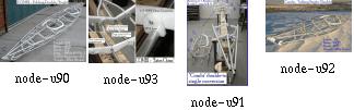
Construction is of aluminum tubing and HDPE "snap-on" cross-sections. Coaming, footrest, and backrest are of these same materials.
Assembly time is under 40min.
Two skins are required, but it's is a small price to pay for two kayaks with the construction time and cost of one.
Folders are already versatile kayaks, but with the addition of this conversion feature, the versatility is extended greatly. Add a folding sailrig and you have the "Swiss Army Knife of Kayaks".
With this design, I wanted to reduce the height of the deck stringers. I always wondered if the one-hatch baidarka deck design really is the big thing, partly because I am making foldable baidarkas:
Surely the Aleut people had their ways to cope with that, but I was struggling to make my craft seaworthy. According to today's accepted safety standards. I had to change it in order to get a foldable design, and the result of this are waterlines very alike to those of the Greenlanders.
Well, this looks like something. I made a good rear hatch, with the pump installed and everything, skipped that rear deck stringer and now have a nicely fitting tilted cockpit. Seems like progress.
Click here to get responses from folks on the "baidarka list" to this.
The pump mount I was talking about. Just flat and within a deck hatch, removing the pump for better loading is easy. This way of mounting the pump doesn't need any hoses which greatly enhances water throughput.
The compass mount I was talking about. Just flat and within a deck hatch, the compass is allowed to recede into the hole. Watertightness is guaranteed by use of a rubber inner tire, which also acts as a spring to pop up the compass.
The rudder control and mast assembly. The rudder pedals slide on the bottom stringer. For the mast, there is an extra hole in the skin...
The rudder blade swivels around a support at the bottom. This reduces exposed rudder blade area when the blade is removed from the water.
All parts of the Greenland Baidarka.
Watch out: the next page contains a 2.1 Megabyte animated GIF!This file is viewable with xanim (animated GIF player) and with netscape. But the file size is 2.1 Megabytes! The whole shebang has to be downloaded before the animation really starts running; this may take several minutes.
Here you will see how the baidarka is assembled from a more distant point of view. This animation is specially useful for newcomers. Just keep in mind that the assembly happens within the skin, but is shown without the skin for clearance.
Pictures of my brother amd me assembling the kayaks within the skin are shown here.
The next slides are large animated GIFs. Loading the animations takes some time. Therefore I have cut the assembly process into parts.
This whole shebang is available on a CDROM, including several other web sites. It is made by Charles Hall and distributed for production cost. The next slide rsp. parts are:
From:
John Winters
Wolfgang Brinck
Christopher Hufford
Philip Wylie
Since the Aleuts didn't have compasses or bilge pumps and many didn't bother perfecting the roll to quite the same degree as the Greenlanders, the ridged deck was not a handicap. I have read an number of "reasons" for the ridged deck (Wolfgang is probably our best source for what might or might not be valid) but I can see no reason why it is essential given our modern style of paddling and emphasis on rolling.
The Kotzbue Sound boat (Fig 186 in Chappelle and Adney) has a flat stern deck as does the Point Barrow (Fig 187). If one is building for purely practical reasons I see no reason to adhere to the ridged deck (or any of the non functional aspects of native designs). Build what works.
The high crowned deck does not necessarily make a boat more seaworthy. One simply needs enough crown so that water will not pool on deck and this is not a lot since the boats are very rarely level anyway.
Cheers
John Winters
Redwing Designs
Specialists in Human Powered Watercraft
http://www.onlink.net/~jwinters
A few comments on decks:
Ridged decks may have more to do with storage capacity than with anything else. Under normal operating conditions, the kayak's bow rises out of the water before water has a chance to come on deck. This is true for flat decked as well as ridged deck boats. Water on deck is mostly an issue if you paddle into breaking waves. On a flat deck water rushes the length of the deck, smashes into your chest and splashes up in your face. It is the wet face which is more disconcerting than anything else. In larger waves, the force of the water can also be quite unsettling. In large breaking waves you will get wet regardless of whether your deck is ridged or flat.
There are two caveats about flattening the deck of a baidarka. The first is that you balance sail are fore and aft of the cockpit or your boat will tend to weathervane. The second is that on some traditional baidarkas, the depth to sheer, i.e. the distance between your ribs and the tops of the gunwales is so low that if you flattened the deck, you could not get your legs inside the boat. Consequently, you would have to make the hull deeper which makes for a tippier boat. When you lean a kayak, it tends to keep leaning until you submerge the rail at which point it starts offering some resistance. In a deeper boat, you have to lean farther before you submerge the roll, hence a larger range of instability. I don't know if this is a good explanation, but I know from paddling deep hulled baidarkas that they feel less stable.
Mark Rogers who teaches baidarka building classes in Whitelaw Wisconsin has his students make boats with raked cockpits, that is, higher in the front and lower in the back. This makes getting in the boat easier and it makes rolling easier. As far as I know this is an effective alteration to the traditional baidarka design. Rolling of a baidarka with a ridged deck is really not a problem. You can do more tricks with a flat decked Greenland boat, but your basic get you up and out of the water roll works perfectly fine with a baidarka.
> Well, I'd like to know if you can lay down on the rear deck while seated.
At least I can't. My coamings all are too high for this. No, I cannot lay down on the rear deck of the baidarka. I don't think anyone can. However, I can slide forward to lower my center of gravity when I roll. The most extreme case I have seen of this is an old film of a King Islander rolling with a single bladed paddle. He slipped almost completely into the kayak before rolling up, then slid upright again after the roll. Of course, my baidarkas are not big enough for that but I can lower my center of gravity a little by sliding forward. I think the key in any roll is to figure out how to keep your center of gravity low while you bring the boat to more or less upright position so you can sit up without capsizing again. I think in a baidarka you have to keep your body low over the side and back while you roll up since you can't get it low on the rear deck.
From: Christopher Hufford
I've been listening to list for awhile and while I'm landlocked in a desert... ;) I did see some baidarka designs in Long Island when I was going to college up there. Maybe this will help...
The designs I saw had a dual ridge at the points where the hatches were, sort of like sideways "Y"s around the hatches. I don't have any direct info as to how the kayaks performed, but the owners told me that the Y's were structured to take the stress and flex as the single ridge did... and they domed the hatches. Also, where the compass mounts in front of the cockpit was a removable (folding version) aluminum block that had a countersunk compass mount with a bubble and a ring guard-clamp that accommodated the skins they were using (some kind of plastic).
Anyway one design had a hole in the skins and the ring guard-clamp screwed down on it sealing it water tight. The other had a clear piece of plastic (the owners said it was harder to see through the plastic at night in bad weather. In either case they had used LEDs &/or pea lamps with a med. rechargeable battery and attached a bunch of solar cells from radio shack (yuh).
They had had a bit of trouble with compass breakage and made the mounting ring to deflect hits. Hope this helps...
Hendrik, Having reviewed your note and concerns over the location and operation of the hand pump this is my suggestion. Why not sell the pump. Install a foot operated pump (Alex Ferguson in NZ is the guy to talk to about this) thereby you are hands free to paddle your kayak while negotiating difficult seas and not worrying about another capsize. Alex paddles some really tough seas off of New Zealand and he also has a superb design for rudder peddals superior to the North American kind. The matter of foot pumps has come up before and I am fully persuaded that they offer the best solution while in the water.
For more about Tony's Taxi on Quadra Island, click here
Just wanted you to see how small a Feathercraft kayak is when packed. Photo taken in the rain at Pagosa Springs, Colorado.
The Feathercraft K-light is so compact and light that it's pack will fit nicely on the back of my motorcycle. The first time that I assembled the feathercraft I was concerned that it was simply too light and flexible. I have since taken it to British Columbia as well as New Zealand. It has performed beatifully in some of the roughest conditions I have ever experienced, especially in New Zealand. The boat I am now building is constructed of heavier tubing. Pic and text by Thomas Yost
For more about Tom's kayaks, click here
You might easily take the foldables in the floatplanes; we just didn't have the money to do so.
The Scandinavian Airline charged my kayak as a "surfboard", for a short distance trip, the baidarka bag exceeded the baggage limits. In all my 747 flights, the baggage was free, as long as it was declared beforehand.
Aircraft Transportation: how to paddle an aircraft... This picture belongs to the Northwest Territories' Photo Database. They have 82 inuit kayak photos, which you can find by entering 'kayak' as the search item.
These are boats (and nuts). They fly and ride trains and buses at no extra fee (the boats, not the nuts).
Transportation
Carrying the kayaks in airplanes, trains, buses and taxis was no problem;
all american transportation had facilities to handle bags of that size.
Even with the Victoria Clipper, from Seattle to Victoria, this was no problem,
although they had all their staff carrying our luggage on board. It might
become one, when everyone tries to carry luggage of that size...
When will YOU pack up and leave?
This is how it's done:
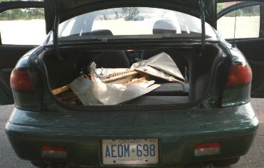
Tom has built approximately 15 boats since 1975, with the first 8 being woodstrip/fiberglass sea kayaks. Of that group, two have been Aleut designs constructed from David Zimmerly's offsets in his book "QAJAQ". He built them to scale but made changes to the deck shape. In addition, Tom built a woodstrip version of George Dysons double .
Having grown a bit tired of building woodstrips, he decided to try a hand at non folding skin boats. He first made three George Dyson singles, the first two of all wood construction, and the third using wood cross sections with aluminum stringers.
He immediately realized that these were more seaworthy than were the woodstrip hulls. The flex in the skin and the concave skin shape between stringers, really slowed down the roll rate as well as allowing the hull to conform to the waves.
Above is a photo of the folding single that Tom was building 1998(?). You will notice a striking similarity to the "Feathercraft" designs. Since he paddles a Feathercraft K-Light, the similarity is no accident. You will also notice that there are very few parts. This boat follows the KISS principal. ( Keep It Simple Stupid)!
The tubing is all 3/4 in. Aluminum 6061/T6 thin wall. The tubes are attached to the Cross sections using "L" shaped brackets pop riveted to the tubes. The frame weighs about 15 lbs and takes only a few minutes to assemble. The frame has a single stretcher bar at the keel. The skin will be made of 14 oz. pre-shrunk nylon. The material will be coated inside and out with three coats of black Neoprene. The deck will receive additional coats of white hypalon to provide a light color. The boat is 15.5 ft (4.73m) long by 24 in. (61cm) wide.
Tom plans to use zippers along the deck ridge for closure and sewn in sponsons to assure a tight fit and to provide additional stability.
Thomas YostAt least in my case, the zipper/sponsons solution has worked more than once. Just take care.
This is the Dyson designed folding double that Tom built a few years ago. This boat took about 3 hours to assemble which most of us consider unacceptable, but at least Tom and I have had the strange pleasure to deal with that. At construction time of our first folders, we both had never seen a folding kayak that we just could copy. We were therefore forced to develop our own solutions and certainly learned much from building our first boats. This photo of Tom's Baidarka taken at Tofino, BC.
Length 21 ft. Width 28 in. Weight 65 lb. Construction time: 150 hr. More kayaks
built by TomTom included all six chines and all 11 or 12 cross-sections which made for a slow assembly process. The skin laced at the deckridge which further slowed down the process. It took about 3 hours to assemble the boat which was simply too long. However, the remarkable thing was that due to the extra flexibilty of the hull as compared to his non folding skin boats, this turned out to be the most seaworthy boat Tom had ever constructed. The flex was very noticable, but the boat conformed to the waves beautifully. It handled all conditions better than the Dyson Woodstrip double which was the same design. (especially in rough water.) Like most of us, Tom once believed that "rigid" was better but trial and error have shown that's wrong ! This photo of Tom's two-seater Baidarka taken at Tofino, BC.
Length 21 ft. Width 28 in. Weight 65 lb. Construction time: 150 hr.
This photo of Tom's two-seater Baidarka taken at Tofino, BC.
Length 21 ft. Width 28 in. Weight 65 lb. Construction time: 150 hr.
Rear construction of Tom's two-seater Baidarka. The inset shows how Tom laced the skin and used a velcro seal to prevent water from coming in. At least in my case, this was not completely watertight. Take care. On the other hand, this is what I also used for the first try, and I guess many more of us did so. It works.
Length 21 ft. Width 28 in. Weight 65 lb. Construction time: 150 hr.
This George Dyson designed non folding Single has aluminum stringers with wooden cross sections and ends. This combination works better than either all wood or all aluminum. Wood cross sections are easy to make and add a warmer feel to the boat. Aluminum tubing is easier to work with than wood for the construction of Gunwales, stringers etc.. Dysons method of using Nylon/epoxy lashing certainly provides much strength and rigidity. This is the third Dyson single that Tom has constructed. The others were made of Redwood or pine. You will notice that he doesn't build using a split bow. He finds that it is of marginal value and quite frankly isn't very attractive. Photos taken at 10,000 ft. Turquoise Lake, Colorado. Mt.. Massive (14,300 ft.) is in the background.
Length 17 ft. width 24 in. Weight 40 lb. Construction Time: 100 hr.+
His second folder was an
Aluminum/Wood Dyson Double (1996).
Third was an Aluminum/Wood single (1997).
Fourth was an Aluminum/HDPE single- FAP-16(2002)
Fifth is an Aluminum/HDPE single - TDY-16(2002).
They keep getting lighter, easier to build, and quicker to assemble. TDY-16 will be my first with a Stamoid skin(Ivory). All others have been either Nylon/Neoprene/Hypalon or Polyester/Hypalon.
Length 17 ft. width 23 in. Weight 40 lb.
This Dyson designed Woodstrip Double is made of 1/4 in. redwood strips covered with 6 oz. fiberglass and West Systems Epoxy resin. Tom believes that woodstrip kayaks are the stiffest of all construction types, including fiberglass. The overall wall thickness is the key to this. He uses redwood due to its cost and availability. It has many of the same properties as Western Red Cedar but lacks Cedars color variation. Neither wood works well with other types of resin (Polyester/Vinylester) due to the oils present in the wood. The boat is finished in UV Clear Urethane(Deck) and White Urethane(Hull). Photo taken at Clayquot Sound, BC.
Length 20 ft. Width 28 in. Weight 85 lb. Construction Time: 350 hr.
Gerald's Foldable Greenland Eskimo Kayak
The Well Designed Stem
His way to attach stringers to frames.
Another view at string-to-frame connectors.
Roy Clo Baggerly
I always look for good homebuilts and especially good solutions for detail problems. Send a note and your image to my address or use email with attachments!
MAE 593-76 was built from David Zimmerly's Offsets in "QAJAQ". This is a tippy but very fast boat. I only paddle it on calm days. Photo taken at Clayquot Sound, BC.
Length 19 ft. Width 17 in. Weight 35 lb. Construction Time: 250 hr.
I have taken great liberties with the deck shape and the coaming. The large coaming allows easy entry/exit from an otherwise tight fit. The boat was constructed of 3/16 in. redwood and 4oz. fiberglass cloth.
Length 19 ft. Width 17 in. Weight 35 lb. Construction Time: 250 hr.
LM 2-14886 (the single seater in the back) was built from David Zimmerly's Offsets in "QAJAQ". This is a fairly stable and fast design. Once again I have modified the deck shape and the coaming. Finish is UV Urethane. Photo taken at Curecanti Canyon, on the Gunnison river,Colorado. Canyon is 1,000 ft. deep.
Length 17 ft. Width 21 in. Weight 33 lb. Construction Time: 250 hr.
The second boat in this photo is a David Hazen design from his book "A Strippers Guide To Canoe Building". The boat is highly modified in both dimensions and detail. Construction is redwood with pine inlay. Curecanti Canyon.
Length 20 ft. Width 28 in. Weight 85 lb. Construction Time: 350 hr.
LM 2-14886 was built from David Zimmerly's Offsets in "QAJAQ". This is a fairly stable and fast design. Once again I have modified the deck shape and the coaming. Finish is UV Urethane.
Length 17 ft. Width 21 in. Weight 33 lb. Construction Time: 250 hr.
This information is free for personal use (free of charge), but still with full copyrights by the author, Patrick Poirier, 2002.
Not to be sold or used commercially in any form except by permission of the author.
To be distributed in exactly the form presented here with this one following exception:
the author encourages all users of
these drawings to correct errors and
add items as they please
but asks
to receive those modified drawings
before they are distributed further.
The objective of this is to define
a working system that enables
anyone to improve this design
and
still have the author accept and
organize the improvements for the
benefit of all.
I leared a lot from watching the others and got sure that my design needs certain improvements.
| 2.8kg | w/ Expedition Wheels (18cm diameter) |
| 3.2kg | w/ Standard Wheels (30cm diameter) |
Mosher was designed by Jochen Vetterlein and Gerald Maroske.
All parts except the wheels are stainless steel.
and secured by shock cords similar to tent poles.
No loose parts that can get lost!
Three design features are trademark registered. We are a bit proud of our little friend; production is difficult and thus expensive. But it's well worth the price, since nothing on the market equals Mosher's versatility.
I keep receiving questions about making PVC skins and thus have re-edited my comments about it into a single file that is a little easier to read. Now you see a mix of four years old comments with very recent ones.
Questions and comments by others are printed in blue.
The images are clickable and lead to the full-size (original) pages.
[ Skin Material ]
[ Welding ]
[ Skinning Sequence ]
[ About Tape on a Final Skin ]
[ About Temporary Skins ]
[ Lacing Skins ]
[ George Dyson's Hypalon Skins ]
[ Thomas Yost's Hypalon Skins ]
[ Epilogue ]
In short, the idea about glueing PVC is to use lots of thinner (Acetone). I had to test the mixture several days and came out with that it is right when the thinned glue begins to run off the brush by itself. Then apply it minimal two times to both surfaces. After letting the glue get nearly dry, combine the two PVC parts and press them well for some minutes.
For the first prototype I sewed two strips of PVC onto a zipper
and glued these zipper strips at the middle of the deck piece. This feature
was as strange as convenient;
it eased assembly and loading of the boat.
With some grief I dropped this idea and the actual design now has hatches
instead of the zipper. These hatches serve the same purpose except that
it is a lot more difficult to assemble the boat. Also I do not have these
sponsons any more that had to stretch the skin.
Anyway, the www site of STAMOID is http://www.stamoid.com/stamoid or http://www.forbo.com and they have some property sheets about that specific skin material.
The skin comes in doublesided or singlesided PVC covering on a polyester fabric. singlesided weighs 280grams/square meter, doublesided is 430g/m2, tensile strength is better than 1200N over 5cm width.
The singlesided stuff is covered with a dirt protecting finish, which makes glueing and welding impossible and thus has to be removed in the contact area.
Paul Raymond wrote: I stopped at a canvas store today, and he sold me 17 feet of double sided Stamoid for $100, which I think is a good price. Since this is for an aluminum folder, and Hendrik Maroske used it with success, hopefully I will too. I'll find another use for the pack cloth.
Stamoid is what I have used, it comes in both protected and unprotected versions. I suggest to get the thinnest material available, that is, I got the 0.6mm stuff and found it too heavy when glued together, so I talked my supplier into buying 0.5mm stuff for me. There even seems to be 0.4mm material out there, and a way to get material with defects (holes) in it (lots cheaper). This material is so thin compared to my Klepper, how does it hold up on your boats compared to commercial boats? Do you still prefer Stamoid to any other material available?
My most recent Baidarka still is the one from the 1999 Toronto trip. The Baidarka skin was finished late summer 1998 and I must confess I did not use the boat very much since Toronto. I have moved the workshop since, and with it the boat, and since that move the lake is a little more difficult to get to (without car).
Anyway, the pics on this website with several closeups of that particular skin have been made during Christmas holidays January 2002, so you have a guess at how good the skin actually is. It still looks "new enough", is tough as ever and still waterproof. No seams broke.
The skin is nearly four years old, the "unprotected" Stamoid, and ready to go on any trip. I'm satisfied with it. Always cleaned stains before they could wear in (with water only), because without the protection I am afraid to use chemicals to clean the skin.
I see that Tom Yost used polyester material, and then coated with hypalon, which worked well for him, but I wanted to avoid having to use toxic coatings, and the pvc material seemed quicker to skin.
To each one his way looks as the best afterwards. But I would still do it again. It took some time to learn to use a good balance of techniques, stitching, glueing, welding. Basically, my experience with Stamoid and Pattex and Acetone is that if the glue doesn't hold within the first five minutes, it never will. Throw away the pieces that you can and restart. If it holds, it always will. And by "holds" I mean you rip the pieces apart and not the glue fails, but the Stamoid goes apart.
Practice good bonds before doing the skin.
And even more basically the only advice I can give is to really do a few practice runs on the stem and stern pieces with the intention to keep them as samples. This will pay out in the end. Use double sided tape for the first practice run to have a good chance to rearrange things and if you don't want to wait for the glue to settle.
And, talking about abrasion, I cut Stamoid in strips and these were formed with a heat gun to match the curving of the hull before glueing them on over the stringers and where the skin pieces meet.
Generally the heat gun helps a lot to smooth out the results. Afterwards, the warm material is perfectly dry for glueing. It seems that there is some amount of (water or other) thinner in the skin that works against a good bond. Seems to be the stuff that makes the PVC soft.
There's different stuff available for glueing non-rubber zodiacs. 2-Komponent and stays flexible, although quite expensive
Welding is used only in professional applications for truck and tent awnings. I got caught by approximately 3mm material shink per meter as I welded the 5 seams in my hull. Makes funny waves in each section. Took me some time with my heatgun to shrink the whole skin, to take the worst away. :-(
Amateur tools for welding soft PVC without glue, just fabric on fabric, are air guns or the like. Their actual use and temperature operation range seem to fit. Use a rubber wheel on a stick to press the layers together. When it becomes black it's too hot... The professional heatgun that I used only melted the pvc surface without allowing for sticking. Something obviously wrong in my procedure. Welding was Gerald's idea, and for him it worked. My (Hendriks) heat gun did cause some degree of sticking, but not enough to really call this welding. It depends very much on the quality of the skin. If there is anything like "abrasive protection" or "dirt protection" put on it, forget about welding. What becomes black ?? PVC does not seem to change any colour. Is it the glue?? I guess that Gerald was joking. My white PVC just got darker and started fuming. Then it's time to rapidly stop heating. Final question not yet answered: do you stitch only for keeping the pieces together ? In other words, does the skin in its final version rely only on glue lines or is it glued and sewn. I could not really get this out of your description in previous postings.
In my case, stitching was used until the glue bonded permanently. After that time (some 15 minutes), the seams were removed where possible.
All your help is precious: I have just bought wallpaper and a range of water based markers to start the skinning job.
I got the wallpaper trick from Gerald, and it's worth it. You'll easily see how it will be with the PVC, since PVC doesn't have much more stretch than the wallpaper.
One thing about heat gunning:
I never was able to really shrink the skin. It's more like
rearranging it to stress, so that folds and waves remove
themselves. If you would really _stretch_ it with heat,
it will cool off and then be over-stressed and floppy.
So, I used the heat gun only for aesthetic corrections,
not for shrinkage.
Paul Raymond wrote:
Has anyone else had any luck using pack cloth, which comes coated one
side and dyed, and adding additional polyurethane?
Michael Daly wrote:
I have never tried, but wouldn't bother. Coated pack cloth, in addition
to having a urethane coating on one side, has a durable water repellent
coating on the fabric as well. The purpose of the latter is to prevent water
absorbsion into the thread and so enhance its waterproof properties.
I'm willing to bet this coating is what prevents a good bond with the
subsequent polyurethane coatings you apply. You need an uncoated fabric to begin
with, or at least one that has only a "coating-friendly" treatment applied.
Preventing any good bond, exactly. I had oversensitized my right thumb from rubbing the material with Acetone to remove the protection from the glue areas. Definitely NOT the way to go. Although the coating really is good, waterproof and repelling dirt.
Stefano Moretti wrote:
I need much help from more experienced skinners. This will be my first
attempt. I've finished the frame od the foldable with much satisfaction. It is
not wobbly as when I first started.
Congratulations! Now proceed to game level 2 :-)
1) Make hull and sides from one single piece, cutting "V" shaped slots in bow and stern. Seen this picture in FOLBOT virtual company tour.
No way. I also tried this. It is better to do it right, from the start on. Buy a roll of wallpaper and make cutting patterns. Cut the patterns in stripes following the chines, guns and keel.
2) Overlap hull and deck skin over the gunwale chine by more than one inch
Again, its better to go right through it: begin with a large overlap for sewing and then cut it small before glueing. The skin is not easily folded with such thick glue strips.
From my experience, I consider everything too thick that is overlapping more than 3/4 inch or has more than two parts overlapping at the same area
3) cutting deck from mid cockpit to bow, and from mid cockipt to stern, so to reduce the wrinkles and dragging all error towards the cockpit area where the big hole would accomodate much wrinkling. Done this with 3 mm plywood in clc kayaks, should work.
The less glue strips (rsp. easier folding), the better. If you go without deck ridge, there's no need to go with the deck seam. Always proceed to the ends rather than towards the cockpit. Otherwise, you end up having a slack skin at the cockpit.
4) for all unexpected problems and some extra stiffness (still very much debated I know) I would add two small section sponsons just below gunwale.
In my case, both designs worked well. Especially with cold, wet skin, sponsons give you the chance to re-stretch it.
How do you cut and glue around the Aleut stern.
Making these end pieces helps a lot in acquiring the skills to work with PVC. Throw away a piece if you are not satisfied. The next one will come together a lot quicker.
Having made a pair of useful end pieces, the large skin panels are glued over the end pieces, and when all the skin is done I add a nice looking finishing layer over the end pieces, smooting out the curvature and hiding all the seams, glued patches and the rugged connection between skin and end piece.
After having made the skin, I rip out the innermost PVC layer of the end pieces, thereby ensuring that the stem and stern will always slide into them without too much trouble. So, the very first PVC layer for these pieces is attached only very temporarily, with double sided tape or masking tape.
Do your PVC skins have a seperate panel for each Keel to chine, Chine to gunwale, and gunwale to deckridge, or are you able to cover greater areas at once?
Greater areas simplify nothing. They make things more complicated, and if something goes wrong, you'll have to throw away more skin. My boats have fairly high gunwales, more like 'planks'. The sequence is like this ( I began inside-out, here's a sketch, but that is not absolutely necessary):
What weight PVC would you recommend ?
The thinnest/lightest you can get. I have used .6mm thick stuff and next time will definitely use .4mm instead. Because every seam doubles the thickness, and together with the glue it really gets stiff. If you expect trouble somewhere, use the thinnest stuff you can get and apply strips wherever needed. The procedure for the stem/stern I described yields very stiff results.
From now on I assume that you have made a set of good end pieces and are ready to skin. PLEASE, use wallpaper for making cutting templates. Cut strips aligning to chines, guns and keel. (in my case, 6 strips + 1 deck strip). By any means make strips the whole length of the boat. Leave out cockpit rim.
On the inverted hull, sew together the two strips that meet at the keel and go up to the chine stringer.
Sew strips loosely together using 1 inch spacing between seam stitches. Sew only where PVC is cut away anyway. This routine worked best for my Greenland Baidarka with only one chine stringer and the gunwales having an upper and a lower stringer.
I used a twohole punch to make a row of holes at a long side of a large piece of PVC and temporarily sewed it directly onto the frame prior to glueing it to other pieces. This way I could reduce the count of folds in the skin.
Sew the two strips that go from guns to chine to the ones you just sewed together, leaving off the stripe between lower gunwale and chine and thus using large seams over the hole (stitches 5-7cm apart).
Loosely attach the previous mentioned strips to the guns (stapling them on wood frames, using tape on aluminum) and rotate the hull
Sew on the deck strips with a rough seam, stiches some 3cm apart
Use heat gun to remove wrinkles everywhere. Rotate hull.
Use heat gun to stick (weld) the remaining two strips to their place between the lower guns and chine stringer.
Remove the large seams under the two newly attached strips. Use heat gun to partially lift off those strips and reattach them without wrinkles.
Lift one yard of each strip, clean contact area thoroughly, apply "hendrix mixture" and glue them together. Make sure glue line is only 1.5 - 2cm wide. Glueing procedure described later. Work towards the ends of the hull, cleaning and glueing.
Let the glue dry. Cut excess skin at the newly made joints.
Use heat gun to remove wrinkles. Do not generate excessive heat at the glue strips!
Redo the keel seam (the butt type, not overlapping!). Now space the stitches 1cm apart. Cut excess skin. Now the borders of the two skin strips just touch each other.
Use heat gun to remove wrinkles at keel area. Cut keel strip (3cm wide) and lay it over the keel. Use heat gun to smooth it over the keel's curvature.
Remove keel strip, clean keel line, 1.5cm in each side (=3cm wide total).
Remove keel seam for two foot length, glue the keel strip where the seam was, to make it watertight.
Redo gunwale seam. Proceed as with keel.
Glue small horizontal skin strips over the bow and stern to generate the Baidarka's extremities. For Greenland Kayaks, much less work since larger patches usable.
Cut and seal the cockpit area.
Don't forget to make sure there is no "protective impregnation" of some sort over the PVC. Otherwise, you get lots of additional work to clean the glueing areas.
Be meticulous at the cleaning operations.
Always make test specimens and rip them apart to see whether the glue mixture and/or cleaning operation was successful.
Well, "hendrix mixture" goes like this:
- thin the glue until it quickly runs off the brush by itself.
- thoroughly mix
- apply three times, let dry after each application
- contact the parts
My glue is the German "Pattex Transparent", thinned with Acetone. You might want to ask my brother Gerald, who is a chemistry professional, what the american equivalent is.
I put a rub strip over every seam and have had good results.
In my first attempts, I also have put rub strips inside the skin; this is not so good, since skin folds less easy, is more heavy and tends to develop folds. Also I simply cannot glue well on the frame from the inside.
On my first foldable Baidarka, the double sided tape that had to closepart of the deck seam and seal it watertight, became an ugly black smeary, slimy thread after a two-week saltwater session. I'll never do this again...
Now, it seems that most of us just try with the expensive skin (me included), ignoring the possibilities of tape (although I tape virtually everything) and clear plastic. I just always had tried to avoid the additional work involved.
But that can be real fun; here is an account of what can be achieved, if you really want.
Tom writes:
This temporary folding skin is made of PVC to test the
viability of the material as a one piece hull.
In this test, I've pulled the skin fairly tight using
squidding line but am careful not to
over stretch. There are still a few wrinkles in the
skin, but to this point no heat has
been applied. The "Real" skin will be made of higher
quality, thinner, Stamoid PVC.
This is a good picture. I have seen this quite often with my own first PVC skins.
My own experience at working with very large PVC skin panels is that bulges develop at the few remaining seams which show that the skin doesn't fit closely. These bulges were quite sharp since in the other places the skin would fit very smooth. Afterwards it was impossible to remove these bulges.
If you look closely, you will see the vertical folds in between the gunwales and stringers. This is exactly the problem zone, they tend to concentrate right before and after the cockpit. On the other hand, the keel area looks good... how about a single piece for both keel panels? Now, the keel needs a rub strip anyway, so there is also no real advantage in doing it in one piece. Doing it in two pieces yields much smoother stem and stern parts. You will find that narrow PVC panels are much easier to work into a pre defined shape.
My own conclusion is that a one-piece skin is perfect for testing the frame before doing the final skin. This one took less than three hours to make. Very motivating.
Tom writes:
The Stamoid has unidirectional fibers which would only conform
in one direction, so it wouldn't take the shape of the hull
without getting all wrinkled at the stringers. In addition, and
the thing that bothered me the most, was the fact that the Stamoid was easy to tear when I
pulled on the stitching that I used to stretch the skin. This
happened in only one direction , parallel to the fibers.
I've never had a skin material
tear before, so it really caused me concern.
I still feel that a one piece PVC hull is workable, as it has been
done by others. The problem I had was trying to do it with Stamoid.
The black PVC had
multidirectional cloth , the same that I use on my sewn skins, so it had
the ability to conform to the stringers. I didn't have enough of it for
the entire boat so I
purchased Stamoid thinking it was made the same way. It wasn't.
About the Stamoid tearing easily when sewn; that is a good point. If I recall correctly, the thicker 0.6mm variant would not tear as easy as the 0.4mm one. Anyway, I had no other comparison and was satisfied with the 0.6mm stuff. Although I have never seen a skin tear on my boats, even on tar or stone beaches. And back then I simply took it as normal, but shame on me, I have used only a small amount of really thin Stamoid, mostly using the 0.6mm material. I stand corrected in having said the thinner material is better. Maybe the thicker material has a stronger cross weave respectively more cross weave?
Here is what I found today, 28OCT2002 when measuring the tearing resistance with a thin line that I would use for sewing the skin (25kg test Dacron). I punched the "sewing" holes an inch from the border and an inch apart:
Direction crosswise to roll length (in roll axis):
20kg,18kg22kg (average=20kg)
Direction following roll length, that is, the fibers,
if fabric were of unidirectional fibers:
12kg,14kg,20kg (average=15kg)
To me the difference doesn't look so alarming, but yes the Stamoid actually is not at all multi/bi directional.
During my boat building runs I noted a rather large variation in quality even in a single roll. Also, the material sample I just have tested is 0.55mm thick instead of the supposed 0.6mm. The resistance to tearing with a strong line also varied a lot and was kept at bay in using a small distance between stitches. In the end I glued everything anyway. Also I used to use a thinner, weaker 10kg line that would rupture before the skin would tear and would not interfere with glueing.
I never could achieve anything with "lots" of heat shrinking on Stamoid. Only with narrow strips that were formed with the heat gun. Heat only re-aligned the weave within the PVC very lightly.
I also have heard of several people trying a one-piece skin, but my own results were frustrating (see above). See here for Patrick Poirier's results.
I know several people who have used hypalon on folding skins and I haven't heard complaints. Of course, commercial folding kayaks and most inflatable boats also use hypalon coatings, but those are impregnated under pressure and thus bonded more completely. But it is a good sign that the river rafting industry has stuck with hypalon for at least 20 years.
I should have all kinds of free time since I finished my new book, but I still haven't found time to revive the BHS. Fortunately, the skin boat revival has a life of its own, and is doing fine.
There's an excerpt of my new book, with discussion, at:
best wishes,
George B. Dyson
Click here for a
view of a Thomas Yost's design for a folding Hypalon skin.
Click here for a
view of a very easy method of lacing the skin to the frame.
"what's that"
I answered "my boat".
"a boat?"
"yes. It's a Baidarka." Having said that I thought he'll ask something about what a Baidarka is. Especially some question about that bow. Instead came
"why'd you wrap your boat in plastic?"
Back in the mid 70's some friends put together a one man hot air baloon made of ''visqueen'' 3-mil plastic sheeting. It was held together with brown packing tape, the same stuff that you use for wrapping packages for UPS.
It was not meant to be something that would be flown often; just a couple of times and then that was it; just wanted to see if they could do it. Of course, the flights had to be done on a tether. The ''pilot'' sat in a plastic kitchen chair with the 20pounds propane tank on his lap.
They started off with a couple of 100 foot rolls of plastic and arranged them in an X pattern on the ground and then started taping the edges together to form the envelope. All of the seams were overlapped and taped on both sides inside and out. One has to size the envelope so that it would have enough lifting power to get the whole thing off the ground without having the inside temperature get above 212 degs. Figuring that anything above that and the plastic envelope would start getting weak and begin to melt......
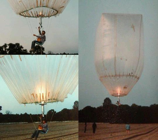
So, all you need is a case or two of tape and a trip to the hardware store for some painters drop cloths...
| Material | PVC |
| Diameter | 7,5 m |
| Volume | 220 m³ |
| Helium fill | 208 m³ |
| Air reservoir | 12 m³ |
| Total Mass | ca.60 kg |
| Carrying Capacity | ca.140 kg |
| Length | 15,6 | m |
| Volume | 109 | m3 |
| Mass | 98 | kg |
| Diameter | 4 | m |
| Stabilizer Span | 4,4 | m |
| Speed | 46 | km/h |
| Altitude | 1000 | m |
| Solar Panel Area | 7,02 | m2 |
| Solar power | 1123 | W |
| Motor Power | 1500 | W |
| Propeller rpm | 800 | 1/min |
| Propeller diameter | 1,7 | m |
Once you've got a set of nice end pieces, do the cockpit section. When you're finished with that as well, you may start the real skinning. With this previous experience, you already have programmed the properties and behaviour of PVC in your mind, thereby much easing work with the large pieces. Once the large pieces are on, I cover the ends with another set of pieces, now completely smoothing out everything where necessary, with sandpaper and a heat gun.
From now on, all strips are being permanently glued together.
Don't forget to work at both sides to achieve a symmetric result...
Remove duct tape, take it off, remove provisional strips, put it on again and permanently glue the keel strips together, using a new strip glued on top of these.
I have used lots of double sided tape to do the show here!
Now, I don't think you should exactly follow my routine. Matter of fact, I don't care at all if you do or not, or if you have a better secret solution. This is no black magic at all. If you have something nicer, faster, prettier or whatever, come up with a few pics and I'll include them here.
What I definitely suggest to you is that you do the same trick as I did just now: run a trial assembly with duct tape. That's a lot of fun to do, very instructional, and you always have a chance to step back, check your work, remove what you just made and redo the last step. This will rapidly tell you the properties of the material you're working with, at minimum cost and time.
Be careful playing with duct tape on skin that will later be permanently glued: you will have to extra thoroughly clean the seams to remove 210 percent of the tape stains, because they interfere with the glue.
Now, let's examine my old PVC skin for an example of how it looks like when it's finished.
This is a good picture. I have seen this quite often with my own first PVC skins.
My own experience at working with very large PVC skin panels is that bulges develop at the few remaining seams which show that the skin doesn't fit closely. These bulges were quite sharp since in the other places the skin would fit very smooth. Afterwards it was impossible to remove these bulges.
If you look closely, you will see the vertical folds in between the gunwales and stringers. This is exactly the problem zone, they tend to concentrate right before and after the cockpit. On the other hand, the keel area looks good... how about a single piece for both keel panels? Now, the keel needs a rub strip anyway, so there is also no real advantage in doing it in one piece. Doing it in two pieces yields much smoother stem and stern parts. You will find that narrow PVC panels are much easier to work into a pre defined shape.
My own conclusion is that a one-piece skin is perfect for testing the frame before doing the final skin. This one took less than three hours to make. Very motivating.
Tom writes:
The Stamoid has unidirectional fibers which would only conform
in one direction, so it wouldn't take the shape of the hull
without getting all wrinkled at the stringers. In addition, and
the thing that bothered me the most, was the fact that the Stamoid was easy to tear when I
pulled on the stitching that I used to stretch the skin. This
happened in only one direction , parallel to the fibers.
I've never had a skin material
tear before, so it really caused me concern.
I'm not sure, but didn't
Patrick make a one piece PVC hull using regular PVC ?
I still feel that a one piece PVC hull is workable, as it has been
done by others. The problem I had was trying to do it with Stamoid.
The black PVC had
multidirectional cloth , the same that I use on my sewn skins, so it had
the ability to conform to the stringers. I didn't have enough of it for
the entire boat so I
purchased Stamoid thinking it was made the same way. It wasn't.
About the Stamoid tearing easily when sewn; that is a good point. If I recall correctly, the thicker 0.6mm variant would not tear as easy as the 0.4mm one. Anyway, I had no other comparison and was satisfied with the 0.6mm stuff. Although I have never seen a skin tear on my boats, even on tar or stone beaches. And back then I simply took it as normal, but shame on me, I have used only a small amount of really thin Stamoid, mostly using the 0.6mm material. I stand corrected in having said the thinner material is better. Maybe the thicker material has a stronger cross weave respectively more cross weave?
Here is what I found today, 28OCT2002 when measuring the tearing resistance with a thin line that I would use for sewing the skin (25kg test Dacron). I punched the "sewing" holes an inch from the border and an inch apart:
Direction crosswise to roll length (in roll axis):
20kg,18kg22kg (average=20kg)
Direction following roll length, that is, the fibers,
if fabric were of unidirectional fibers:
12kg,14kg,20kg (average=15kg)
To me the difference doesn't look so alarming, but yes the Stamoid actually is not at all multi/bi directional.
During my boat building runs I noted a rather large variation in quality even in a single roll. Also, the material sample I just have tested is 0.55mm thick instead of the supposed 0.6mm. The resistance to tearing with a strong line also varied a lot and was kept at bay in using a small distance between stitches. In the end I glued everything anyway. Also I used to use a thinner, weaker 10kg line that would rupture before the skin would tear and would not interfere with glueing.
I never could achieve anything with "lots" of heat shrinking on Stamoid. Only with narrow strips that were formed with the heat gun. Heat only re-aligned the weave within the PVC very lightly.
I also have heard of several people trying a one-piece skin, but my own results were frustrating (see above). See here for Patrick Poirier's results.
This baidarka assembled without the noise that
my aluminum baidarkas used to make.
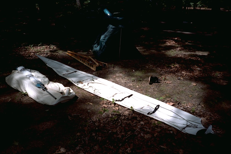
Perfect paddling weather. The way I got there was this: on a Friday noon I was working in England on a piece of software. Already a taxi was waiting to take me to the airport. At the same time, one of my various bosses showed up with a commanding voice and a ticket to Toronto. So I repaired that code, got my plane home to Germany that Friday, packed the baidarka on Saturday and catched the plane to Toronto on Sunday, showing up with a previously undeclared bag of 2m times 50cm times 30cm weighing 90 pounds. It was an eventful check-in, but eventually the bag got on board for about 200 US dollars.
Nearly two weeks later, still in Toronto,
I managed to get a long weekend off, but I would only know that
I am off when I already sat in the car, driving north. Whew.
Sunsets at Killbear are worth the paddle.
This is almost a ritual to me: Aunt Jemimas pancakes.
One last impression of 'paradise'.
Tom writes:
I've just recently completed a new kayak after a few years inactivity. The design is a hard-chine Iqyax (CNM-12212) that I built based on a simplified version of George Dyson's method utilizing aluminum stringers with plywood cross-sections. The skin is 8oz nylon coated with several coats of neoprene/hypalon.
Length - 17.5 ft
Width - 17.5 in
Weight - 28 lbs.
Cp - .61
Tom writes:
With 33 degrees of deadrise and very generous rocker, it is visually very
interesting and has great performance to match.
It lays on it's side up to the gunwales when resting unoccupied on the water.
Seems to support the Veniaminov and Sauer accounts of the Iqyax form.
Length - 17.5 ft
Width - 17.5 in
Weight - 28 lbs.
Cp - .61
The aluminum construction is a nice way to make a rigid baidarka. For folders, I tend towards recommending wood, the Greenland baidarka was a lot easier to make, but my next rigid baidarka will have an aluminum frame again.
Length - 17.5 ft
Width - 17.5 in
Weight - 28 lbs.
Cp - .61
Length - 17.5 ft
Width - 17.5 in
Weight - 28 lbs.
Cp - .61
This is the new, presumably more stable version of CNM-12212, named BIF16.
Tom writes:
I'm currently building a variation of this design but with a greater beam, shorter
length, but the same displacement. Deadrise is about 29 degrees on this version.
This building method takes only about 70 hours to complete.
Boatbuilders out there, take not only a close look at this design; also notice the nice setup, sawhorses and beam - Hendrik
Length - 16ft
Beam - 20.5in
Depth - 12in.
Deadrise - 28.5 deg.
Cp. - .58
Weight - 26 lbs. (est.)
Displacement - 185 lbs. (5.2in waterline)
Tom writes:
I built a large workshop which has made boat building more enjoyable
than the dark basement that I used for
so many years.
Length - 16ft
Beam - 20.5in
Depth - 12in.
Deadrise - 28.5 deg.
Cp. - .58
Weight - 26 lbs. (est.)
Displacement - 185 lbs. (5.2in waterline)
Tom writes:
In the past I've used 3/4in X .049 wall thickness aluminum tubing.
Attached are top, side, and front views of CNM-122212 to give you some idea of their proportions.
Tom writes:
Attached are top, side, and front views of BIF-16 (the name I gave the new
design) to give you some idea of their proportions.
I indent the sections 1/4" for the tubing. Computers sure make it easier
than when I had to do all the fairing by hand.
For the new design, I'm using 3/4in X .035 walls. It's both lighter and more
flexible. 84 feet of this tubing weighs only 8 lbs.
I've attached a collage or two showing some details of the finished frame. I'm kind of a Digital camera nut so I take photos of everything.
I've still got to install the seat but just like CNM-12212 I'm going to install a nylon "sling" seat platform with the actual seat being one from my ''Feathercraft''. I like this type of seating as it is easy to make, very light weight, and quite comfortable.
Baidarkanauts take note: the Epoxi pumps are essential for a smooth, decent job.
PS - The wings stored over the workshop [are for a Fisher FP-202 airplane]. I started it several years ago but never finished the project. The photo of the boats includes a Dyson, CNM-12212, and the Lowie Museum boat.
I had asked Tom:
''Did you actually weld the T-piece? This looks interesting.''
Tom writes:
No, what you are seeing is 5-minute epoxy that held
the tubing together until I could lash it with the squidding line.
Actually, I originally intended to make a slot in the bow piece
but opted to use the current configuration to give me just enough
of a gap to allow sewing the skin along the slot between the tubes.
It will still have the benefits of the original but be much less
complicated than the ''Baidarka'' style and should be very easy
to sew in a straight line.
The tubes are the ''slot''. I've never been much of a ''Bifid'' fan.
Speaking of BIF - The name I've assigned this design doesn't refer to ''BIFID''
but actually refers to Baidarka ''Iqyax'' Form (BIF).
Speaking of weight - the frame complete with foot plate and coaming weighs in at 16 pounds. The completed boat should come in at no more than 25 lbs with 8oz. cloth and hypalon.
The sling seat still needs a bit of work as I ran out of grommets for the lacing. I like to be able to adjust and/or move the sling seat if needed; hence the lacing. By the way, final weight is 25lbs. Perhaps I can fill it with Helium and make it a single place Dirigible.
It was too cold and windy this weekend for paddling (at least for a wimp like me). However, the long range forecast is for sunny days and about 50F on Thursday and Friday (Jan 24-25, 2002). Will give it a go at that time !
Good luck!
The name FAP-16 stands for (Folding Aluminum Polyethylene - 16)
This is moving along much faster than I anticipated.
The additional time spent drilling and cutting
the HDPE cross-sections is offset by the fact that
the sections don't get varnished, and there is no need to lash and epoxy
the connection points.
I decided to make the tubing connections at about 40 inches.
The 5/8in tubes fit too loosely to be effective inserts when
used with 3/4in X .035wall. Life is a compromise.
I wrap inserts with packaging tape, the very thin variant, until I get a tight fit. At the connectors, wrap only the stationary part of the piece. Won't help much for the connections, but this way you can slide a snug fitting insert anywhere there's additional strength needed. I've finished riveting the inserts and have almost completed the stern. All that is left to do now includes the bow HTPE connection, deck tubing, and fiberglass coaming.
Time spent so far includes:
Design/Print cross sections - 6 hrs
Drilling/Cutting HDPE - 12 hrs
Tubing (fitting, cutting, inserts, stern) - 12 hrs
I've rounded the Aleut stern more than usual to simplify the building process. That Aleut stern sure complicates the PVC skinning process.
A few weeks later, Tom writes:
Now that the hypalon has cured, I've been able to assemble the kayak.
It goes together very easy.
The skin weighs only 5 lbs. Actually it's less but I was afraid you
wouldn't believe me.
That is very light indeed. My PVC skin usually comes in at about 12 lbs. And complicated it is. To get a good idea about what to tackle with when it is about covering a full aleut baidarka stern with PVC skin, look over here and decide for yourself.
I used a 1000watt heat gun on the deck to remove what few wrinkles there were. The hull too needed very little heat. I was able to make a one piece skin with the temporary deck ridge and stem/stern the only areas requiring sewing. All in all, no more difficult than nylon. Nylon , due to it's superior shrinking characteristics, seems to makes a more taut skin. However, tautness isn't really an issue on a folding skin since it's controlled by sponsons, stretcher bars, zippers, etc.
All that's left to do is apply several coats of hypalon, remove the temporary deck stitching, and install a zipper. I'm looking into waterproof zippers. Sponsons are ready for installation if needed.
Look here for Tom's new, improved version of the skin attachment.
As such, there are no stretcher bars, sponsons or other mechanical devices. This means that the frame is built outside the skin and then the skin is pulled over the frame and laced up.
I intended to use zippers, but the added complexity plus the fact that zippers gave me less space to work with, especially at the stem/stern, led me to a quick lacing system. The lacing system does permit limited tightening of the skin. However, a completely watertight environment isn't assured, although it comes close.
At 35 lbs, a quick assembly time, and no complicated attachments between the tubing and cross sections, I believe I've finally made a folder that's easy to build, easy to assemble, and practical to use. Time will tell.
Frame assembly takes less than 10 minutes but it will be a couple of weeks before the hypalon cures sufficiently so that the skin can be removed and the complete assembly process tested. I'm estimating 20 minutes for frame and skin assembly as there are no stretcher bars or sponsons. The skin has been made about 1 inch longer than the frame to insure ease of assembly.
LOA - 15ft 8in.
Beam - 23in.
Weight - 35lbs
Construction Time - 100hrs.
Assembly time - 20 min.
LOA - 16ft 2in.
Beam - 20.5
Weight - 25lbs.
Construction Time - 75hrs.
This Non-Aleut design is intended as a lightweight medium volume touring kayak. As compared to FAP-16, it features a peaked deck to improve interior room for the paddler as well as more storage space. It utilizes thinner walled tubing (3/4" X .035) and six cross sections ( FAP-16 has seven) to reduce weight. The cross sections, coaming, and footbrace are made from HDPE. Finished weight is approx. 26 lbs.
The skin is a sewn, one-piece Polyester (9 oz.) design, and is coated with Neoprene/Hypalon. The hull is covered with eight coats of neoprene, while the deck is covered with five coats neoprene and three coats Hypalon. Neoprene is a bit easier to apply than Hypalon. It cures quicker, and is more durable. Hypalon has the advantage of being easier to fold, and is available in many different colors.
The following pages highlight only those construction details not included with, or that differ from FAP-16:
Stem, Stern and Frame
FAP-16 and TDY-16 Frames
TDY-16 Frame
Coaming Details
The HDPE coaming is comprised of 1/4" baseplate, 1/2" coaming, and 1/8" coaming lip.
Machine screws are used to provide a secure coaming attachment.
Polyester Skin (9oz.)
The one-piece Polyester skin is sewn with nylon squidding line.
The deckridge and stem/stern are cut (seared)
with a propane cutting blade prior to sewing. This process
assures a hard edge that will not separate.
The deckridge will be cut open for the installation of lacing or zippers.
Neoprene
The frame is first waxed to insure that neoprene will
not soak through and stick to either the aluminum or HDPE.
Before coating , a heat gun is used to remove wrinkles
still remaining in the skin after sewing.
The first two coats of Neoprene are thinned with 10percent
Zylene to insure that the neoprene will soak deeply
into the polyester cloth. Subsequent coats are thinned
but to a lesser degree.
Neoprene is applied with a 3 or 4 inch brush. Use short brush strokes and be sure not to brush the neoprene once it starts to glaze over. That will cause ripples in the surface. Maintain a wet edge and move quickly along the surface. Subsequent coats of neoprene can be applied every 30 minutes or so.
When the skin is removed, the inside hull will receive 2 additional neoprene coats. This is not necessary, but will insure complete saturation, and makes for a better looking job.
Always wear a respirator, and work in a VERY well ventilated area.
Hypalon
After applying neoprene, the deck or hull can be coated with
additional Hypalon to give it a color other than black.
Hypalon cures slower than neoprene and requires a longer
wait between coats. Hypalon stays slightly tacky
for a few weeks. Adding Lacing, zippers, flaps, and deck
rigging can be done in a week or so after coating.
Wait several weeks after coating before removing the skin.
I normally wait a couple of months before folding the skin.
The main advantage of the Polyester/Neoprene/Hypalon skins are their one-piece construction and ease of repair. An additional coat of Neoprene/Hypalon every couple of years will keep it looking like new.
Rub strips can be glued to the keel and chines for added durability.
Skin/Coaming Attachment
On FAP-16, the skin to coaming attachment is accomplished
by wrapping the skin under the baseplate and using snap connectors
(see here for the idea).
On TDY-16, the skin is attached directly under the coaming with machine screws and recessed snap connectors. This is a cleaner installation, but the other method is easier.
Finish
At this stage, all that is left is to install lacing or
zippers, attach the flap, and deck rigging.
The seat is a gunwale mounted sling type similar to that
in FAP-16. A paddling report will be added later.
Neoprene is applied with a 3 or 4 inch brush. Use short brush strokes and be sure not to brush the neoprene once it starts to glaze over. That will cause ripples in the surface. Maintain a wet edge and move quickly along the surface. Subsequent coats of neoprene can be applied every 30 minutes or so.
When the skin is removed, the inside hull will receive two additional neoprene coats. This is not necessary, but will insure complete saturation, and makes for a better looking job.
Always wear a respirator, and work in a VERY well ventilated area.
The main advantage of the Polyester/Neoprene/Hypalon skins are their one-piece construction and ease of repair. An additional coat of Neoprene/Hypalon every couple of years will keep it looking like new.
Rub strips can be glued to the keel and chines for added durability.
On TDY-16, the skin is attached directly under the coaming with machine screws and recessed snap connectors. This is a cleaner installation, but the other method is easier.
The cross sections, backrest and footbrace are made of HDPE. The skin is a sewn, one-piece Polyester design. Coating are Neoprene/Hypalon.
The deckridge is considerably taller than FAP-16 to provide greater room for comfort and storage. Personally, I prefer lower, flatter decks, but wanted to provide an alternative for other builders.
Frame Design
This Aleut based frame is made of 5/8" tubing. Though
flexible, it showed no signs of deflection in the water.
The HDPE cross sections allow for ease of construction
and assembly. The tubing size and number of cross
sections are the same as the Feathercraft
Kahuna (14'6" LOA). Tubing size can be changed to 3/4"
if desired during construction.
Adjustable Footbrace
The footbrace is a combination of aluminum tubing
and HDPE. The three piece aluminum tube telescopes to
attach to the chines with an HDPE "snap" connection.
Sheet metal screws are attached to the chines every
inch or so to allow adjustment points. The HDPE
foot plate is both comfortable and secure.
Backrest
Like the footbrace, the backrest uses a combination
of aluminum tubing and HDPE. The backrest "snaps" onto an
aluminum tube that is affixed to the back of the
coaming. The backrest pivots to adjust to the paddlers back position.
The overall depth of the backrest is 2.5". The
entire unit can easily be removed if not required.
Backrest
Both FAP-15 and TDY-16 utilize a 2 piece coaming
design. The hold down screws attach to plates
affixed to the front
of section 2 and the back of section 3. This
provides a secure coaming mount. The snap-on
connections used with FAP-16 have been eliminated.
9 oz. Polyester Skin
Same design/construction as
TDY-16
and
FAP-16.
Neoprene/Hypalon Coatings
Unlike the Hypalon coated skin of FAP-16, this boat uses both Neoprene and Hypalon.
The hull is covered with 8 coats neoprene, while the deck is covered with 3 coats
Neoprene/4 coats Hypalon.
Neoprene/Hypalon Coatings
FAP-15 and TDY-16 curing on the racks. At this point,
deck fitting have not yet been attached.
Both boats have since been paddled, but no pics are
available since my digicam is in the shop for repairs.
I'll provide a report with pics at a later date.
Table Of Offsets
I've chosen not to post offset numbers until the sailrig is thoroughly tested.
If all checks out, or if design modifications are necessary, I'll post them at that time.
Amas - (Folding)
This ama design is based on, but not a copy of, the Chesapeake
Light Craft Eight Footers that appear
in Woodenboats #131, July/August, 1996. The CLC amas are
made of plywood and feature a "V" shape cross section.
The SPY-10 folding ama utilizes aluminum tubing with a
nylon/neoprene skin. The cross sections are "Hard-Chine".
The amas are 10 feet long to approximate other designs currently in use.
With 3 cross section and 3/4"X.035 tubing, the amas weigh 7lbs. each. Estimated weight with Nylon/Neoprene skin is approx. 10lbs. each. The 120lb. displacement figure is at point of submersion.
AKAS
The twin 10 foot akas are made of 1.5"X.049 tubing
and break down into three sections. The center
section is 4 feet, and the outer sections are 3 feet each.
There are two 27" inserts per aka, which are made of
1-3/8"X.058 tubing. The akas are spaced six feet apart
as I felt that was a minimum distance for paddle
clearance.
My workshop is pushed nearly to it's limit when the sailrig is assembled.
HDPE Sailrig Components
The front aka attaches to cross section three and
the rear aka attaches to cross section six of FAP-16.
The original cross section six was remade, and moved 7"
forward to allow attachment to the rear aka. All components
of this system are made of HDPE. HDPE cross sections
were chosen as the main attachment points for the akas,
due to the integral strength of the cross sections.
There are also attachments at the Gunwales to help distribute the load.
Leeboard and rudder pics and descriptions will be posted upon completion.
Sail/Mast
The sail and mast will be purchased from a commercial sail
maker as I have no practical experience in that area of construction.
A 36-38sq.ft. sail is recommended.
Aka/Ama Assembly
The akas/amas attach with one 1/4" bolt per attachment
point (four). There is an HDPE "cradle" attached to the
aka that holds the ama in position, while also
allowing the ama to sit at six degrees off vertical (CLC specs.)
Sailrig Assembly
The SPY-10 sailrig attaches to the FAP-16 cross sections with three 1/4" bolts per aka.
Assembly takes only a few minutes. The three aka sections assemble with 1/4" bolts.
This folding sailrig should add another dimension to the already versatile FAP-16 folding kayak. The uses for HDPE seem endless....
Many Thanks To -
Mark Balogh of "Balogh Sail Designs", who determined the proper mast/aka location http://www.baloghsaildesigns.com
Tony Niilus, who provided much needed sailrig design input. http://www.geocities.com/niilus
Paul Ernst, whose vision of a folding sailrig got me started on this project. He is the first builder to complete one of my kayak designs (FAP-16), and is currently working on his second.
Hendrik Maroske, whose kindness and hard work, have made it possible for me to display my designs on this great folding kayak site.
With 3 cross section and 3/4"X.035 tubing, the amas weigh 7lbs. each. Estimated weight with Nylon/Neoprene skin is approx. 10lbs. each. The 120lb. displacement figure is at point of submersion.
My workshop is pushed nearly to it's limit when the sailrig is assembled.
Leeboard and rudder pics and descriptions will be posted upon completion.
Sail/Mast
The sail and mast will be purchased from a commercial sail
maker as I have no practical experience in that area of construction.
A 36-38sq.ft. sail is recommended.
Sailrig Assembly
The SPY-10 sailrig attaches to the FAP-16 cross sections with three 1/4" bolts per aka.
Assembly takes only a few minutes. The three aka sections assemble with 1/4" bolts.
This folding sailrig should add another dimension to the already versatile FAP-16 folding kayak. The uses for HDPE seem endless....
Many Thanks To -
Mark Balogh of "Balogh Sail Designs", who determined the proper mast/aka location http://www.baloghsaildesigns.com
Tony Niilus, who provided much needed sailrig design input. http://www.geocities.com/niilus
Paul Ernst, whose vision of a folding sailrig got me started on this project. He is the first builder to complete one of my kayak designs (FAP-16), and is currently working on his second.
Hendrik Maroske, whose kindness and hard work, have made it possible for me to display my designs on this great folding kayak site.
:=)
This here is a suggestion for a very-quick-and-dirty method of comparing kayaks.
I am basically suggesting to compare apples and potatos, but that is all
I was able to exchange with all you other builders until today. So be it.
To be honest about what is done here, I will cite Peter Chopelas in the
Baidarka mailing list:
''Your method of 'testing' the flex is not even remotely similar to what happens in the water.''
Anyway, there are several methods used, and it seems that everyone sooner or later ends up with doing one of them, and not recording the results (which is even worse!), so I'll show them here in hope of eventually getting someone to have paper and pencil ready, and in the end come up with useful data.
Without any numbers given, the value of the statement is minimal. But that's what I did with about every kayak I made, so at least I can say that my own creations bent noticably; in fact, so much, that I did not repeat the test too often. Next time you do this, have somebody at least eyeball the deflection!
ve_hengda_smith@yahoo.com. ''[...] and wondered how flexible they really are. I measured deflection under load at each stage of construction and; here's the procedure I followed and what I found:
The gunwales were supported the outside of the first deck beam at either end and a 40 lb load was applied at the masik, which slightly overstates the deflection that would occur with the driver in the standard position; I figure this doesn't matter because the masik is a convenient reference point and the data aren't being used for calculations of anything important. Measurements were taken between the top of the masik and the floor. If I had been more thorough, I would have recorded the distance between supports and a lot of other relavant data; maybe next time. Lashing was done with a flat, waxed nylon tape called "synthetic cat gut" (available from Tandy Leather)where it would contact the skin and with nylon seine twine where it wouldn't. All lashings were pulled as tight as I could get them, and the seine twine was epoxied after completion.Measurements should be accurate within +/-.031 and are expressed to the nearest 1/16th.''
1. Assembled deck-deck beams lashed, end blocks temproarily screwed in
place with four #10 wood screws at each end.
| Force | Displacement, frame only | Displacement, frame in skin |
| kg | cm | cm |
| 0 | 0.0 | 0.0 |
| 5 | 0.3 | 0.25 |
| 10 | 0.6 | 0.6 |
| 15 | 1.0 | 1.0 |
| 20 | 1.4 | 1.25 |
| lb | inch | inch |
| 0 | 0.0 | 0.0 |
| 10 | 0.12 | 0.10 |
| 21 | 0.24 | 0.24 |
| 31 | 0.4 | 0.4 |
| 42 | 0.55 | 0.5 |
What I see here is that the flexibility does not change much with the skin on; but this is for a folder and with small loads. Anyway, it is a result that I would not have predicted before doing the test. Still, the following remarks are true:
From: Bob Klemick
''[...] With the skin
on it will still flex the same but it takes much more effort.''
From: Peter Chopelas
''[...] The skin will make a big difference, but also the way you are loading it
is far more severe than what happens in the water. The water supports the
hull distributed among all the frame members.
Also consider that the support the water gives is distributed according to
the water displaced. So the widest and deepest part of the hull, right where
the seat is, is what provides most of the support. Which is also right where
most of the weight is concentrated. The ends, where you put your blocks,
do contribute some support when in the water, but it is a very small
contribution compared to the central part of the hull.
There is no easy way to make this comparison unless you have a frame
only (without the skin) of a hull that you know has the right amount of
stiffness.''
The reason for my putting the blocks 4m apart is to get measurable results with small loads; I would not load the bare frame with more than 20kg, because some of the folding hinges depend upon the skin to keep them from falling apart.
Perhaps the only advantage of a folding kayak is that I can compare the bare frame against the complete kayak any time. Although the applied loads seem to have been too small to generate the results I would have expected, I can assure you the flex of the assembled folding baidarka is adequate for good paddling characteristics; so, if you should ever repeat these measurements with your frame, if you end up with what I got, it is no guarantee for success, but at least a hint that you are not completely off the ballpark.
The mid diagram shows what the DMS probe looks like (not much to see though).
The right side shows the winch. This is a dirt-cheap garage winch with a brake. The brake is the most important part of the test rig: it ensures a constant load when necessary (for calibration!). Just stop the motor, and the brake will do the rest.
My own recommendation to myself is, if I need the results because nothing else is available, just divide everything I got from that machine by ten, and that's the maximum design load, including all safety factors. Easy to do, easy to remember.
Also attached is a photo of a test piece of HDPE that I drilled and cut to create a 1/2in opening which is 1/8in beyond the half circle (3/8in) of a 3/4in tube. I certainly wish the US would go to metric for the sake of logic and uniformity. (3/4 = 6/8 = 12/16 =.750in = and so on.)
Anyway, I tested this by "snapping" the HDPE on a 3/4in tube 250 times to see if it would fail ( no snap and hold no more). It worked fine and 250 "snaps" is a lifetime for a folder. I purchased a 4X8ft. sheet of 1/2" HDPE ($175.00 US) which is enough for a couple of boats.
This is the easiest way I know to connect tubing to a folder cross-section. Feathercraft has been using this method successfully for many years. HDPE is easy to cut, and easy to drill. In fact, it easier than working with plywood, much to my surprise. Also, I plan to lay up a fiberglass coaming for the folder.
The difference between "Measuring" and "Lofting" is apparently that lofting is the process of turning the data collected into a working drawing of the station and not the actual collection of the data. Since the Lofting station actually "measures" data (2) and also "Lofts" data (3), the name might be misleading, but hopefully this is cleared up now.
In this sample, I measured Cross Section data from BIF-16, a single chine K-1. I did only one station (Station 5). I measured the keel, chine, and gunwale, but could have captured deckridge data also.
It can't be that easy!
Yes, it's amazing how simple, seemingly complicated processes can be. I came up with this solution over 20 years ago when I had access to a friends Jensen Pro Boat (Racing Canoe). I tried bending soft aluminum tubing around the sections, cutting and pasting construction paper, and even fiberglassing nylon rope before finally "seeing" this solution. Sometimes you just need to step back and look at things from a different angle. For all I know, there could be others "measuring" this way, but I've never seen it done.
1. Lofting Station It is used to capture data (2) from one side of the hull/deck. The captured data is then used to define both sides of the station. If required, the Lofting Station could easily be moved to the other side of the station to measure that data also. In addition, the Lofting Station is used to loft measured data (3) directly to a full-sized working drawing. Another reason for the one sided design is to allow it's removal without disturbing the kayak. You will also note that the cradles for the boat are on stands that are higher than the base of the Lofting Station. This insures that the Lofting Station can move freely along the boat.
2. Measuring Masking tape is used to mark off the station being measured . I'm using only one for this sample, but in practice I captured data every 1.5 or 2 ft. Woodstrips (1/4") are attached to the Lofting Station with 1/2" staples. This length staple holds the woodstrip strip firmly but also permits easy removal. When done with a station, simply pull off the woodstrip/staples and reposition at the next station. Replace staples when needed.
Mark the end of each strip to indicate the point of contact. Slide the Lofting Station under the deck and align woodstrip (A) with the Keel (touching). Once aligned with the keel center, staple the strip to the frame. You could use a pointed strip but it really makes little difference as long as the strip is marked. Do the same for the Chine (B) and Gunwale (C). Once this is done, repeat this procedure with the Chine (B) and Gunwale (C). Next, slide the frame out from under the boat and begin the lofting process.
3. Lofting - "To lay out a full-sized working drawing of the lines and contours of (as a ships hull)."
Tape a sheet of construction paper on the Lofting Station as shown in the photo. In the past, I used a sheet of plywood equal in size to the construction paper to add rigidity. For this sample, the paper alone will suffice. Place marks on the paper to indicate the Keel, Chine, and Gunwale contact points. Once done, move to the next station and do it all again. Be sure to indicate which marks go with what station, or simply use a different sheet of construction paper for each station.
4. Lofting (cont.) Once all stations are measured and marked, place the construction paper on a flat surface/table and use a T-Square to draw line indicating the top of the station at the Gunwale (c), and another one indicating the centerline of the station at the keel (a). Draw a line between the marks for the keel and chine , and the chine and gunwale. For this sample, the "Station 5" keel represents the baseline ( lowest point of keel) although in reality, the baseline may be at a different station. You can now create a complete cross - section if desired by duplicating your results on the other half of the center line.
Since I like to use a "Table Of Offsets", I also record the Height Above Baseline (HAB) and Half Breadth (HB) data. The cross-section drawing in figure 4 displays both the lofted section and it's corresponding Table of Offsets.
Oh yes... end of 2001 I have moved from a 12 foot high 30'x20' workspace with four rows of lights and three large double windows facing west into a basement 20'x12', what a change, the workbench alone occupies the room now. It is a nineteen feet bench; the longitutinals of 4"x4" construction wood, full length. Loved it. But just way too large and obstructed the exit door, no way to get the baidarka in and out except clearing up the whole bench and lifting the kayak over it... so I had to decide to go and cut that bench.
What a SAD DAY
I just hate to cut the wood that was a hassle to transport into the first workspace (in the second floor!) and then into this basement... anyway it had to be done. I ripped the thing apart, trimmed the plate and beams and put one half of it back together.
And then, LIGHTBULB went on: I could just fetch some big metric construction screws, rearrange the parts and the third now useless support frame and bolt the stuff back together. Now it is a matter of minutes to get that third frame out under the bench. It is screwed to the rest by the screws you see on the right of the image. The table plate is supported by new assembly (no heavy loads admitted without support though, but what is heavy for 4x4s), and I can roll the kayak out under the bench; for the purpose I now have made a kayak storage jig with wheels under it!
So in the end that bench is as strong as ever and can be disassembled when the exit doorway is needed. If you are interested, take a look at http://dragonflycanoe.com/stephens/tools_and_materials.html the book is what I have used as a plan. I just took thicker beams, so bulky when seated on the edge they just don't tip over.
Here is the sketch I used as a guide:
We actually have managed to collect a few useful design and construction tips,
and the purpose of this page is to divert you into the appropriate sections, depending
upon your preference.
In the past I have tried to organize these pages by date, boat and builder; I think
the order suited my own necessities more than it does yours. So here is a try to
give a 'crosswise' approach. Not sorted by boat and builder, but by
part and method. Hope it is of use for you.
Since this is a 'crosswise' entry,
you will have to use the button to get back here.
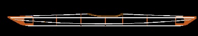
Thomas Yost:
[SPY-10 Folding Sailrig (2002)]
[FAP-15ft (2002)]
[TDY-16ft (2002)]
[FAP-16ft-30lb (2002)]
[Feather-15.5ft-15lb (1997)]
[Dyson Double-21ft-65lb (1996)]
[Dyson Single-17ft-40lb (1993/94)]
Gerald Maroske:
[West Greenland 5m-17kg (1995)]
Hendrik Maroske:
[Lost Soul 5.2m-22kg (1999)]
[Nevermore 5.2m-26.5kg (1997)]
[Last Chance 5m-22kg (1995)]
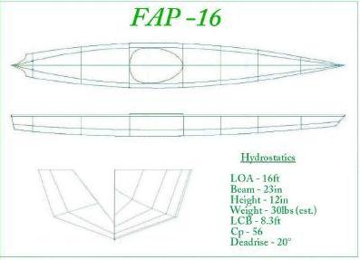
FAP-15 by Thomas Yost: Smaller, wider FAP-16
TDY-16 by Thomas Yost: Folding Aluminum Polyethylene Greenlandic Design
FAP-16 by Thomas Yost: Folding Aluminum Polyethylene Baidarka Design
Lostsoul by Hendrik Maroske: Second Animated Assembly Video
Plan of BIF-16 by Thomas Yost
Plan of CNM-12212 by Thomas Yost
Greenland Kayak Design
Folding Aluminum Baidarka Nevermore: Crude Sketch
Folding Aluminum Baidarka: Try This Tubing Next Time
HDPE Frame and Aluminum Tubing
Testing Aluminum Rivets
Contributors to this page: Thomas Yost (TDY), Patrick Poirier (PPR), Gerald Maroske (GUM) and Hendrik Maroske (HHM)